|
The NanoSensor® is a non-contact position measuring system based on the principle of capacitance micrometry. Two sensor plates (a Target and a Probe) form a parallel plate capacitor. The spacing of these two plates can be measured, using the appropriate electronic controller, to better than 0.1 nm, with a range up to 1.25 mm, a frequency response up to 5 kHz and linear to 0.02%. Because the NanoSensor® is a noncontact method, it is free of hysteresis. No power is dissipated at the point of measurement.
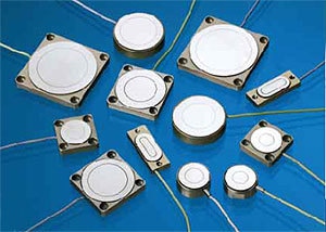
Figure 1. Different nanosensor configurations.
Features
- Subnanometer position resolution
- Zero hysteresis
- Linearity error down to 0.02%
- Bandwidth up to 5 kHz
- Super Invar versions available
- Vacuum compatible options
Applications
- Stage control
- Microscopy
- Structural deformation
- Vibration control
- Materials testing
- Precision engineering
- Space Station Robot Arm
Using the NanoSensor®
The two plates of a NanoSensor® are mounted facing each other with an air gap (G) equal to the measuring range (figure 2). One plate is secured to a fixed reference, the other secured to the moving part to be studied. The sensor measures displacement over the region 0.5 G to 1.5 G (for example a 100 μm range sensor is mounted with 100 μm gap and operates from 50 μm gap out to 150 μm gap). For optimum performance the sensor faces should be mounted parallel to each other – see figure 3.
Figure 2. Schematic of a nanosensor.
Figure 3. Nanosensor output.
Each sensor can be used over two different measuring ranges denoted -L for long range and -S for short range (2 pF and 10 pF capacitances respectively). For example the NXC sensor can be used to measure a 500 μm range with a noise level of 75 pm rms Hz-1/2, or to measure a 100 μm range with a noise level of 5 pm rms Hz-1/2.
The -S or -L operation is determined by the electronic controller; the two measuring ranges are user selectable. The measurement bandwidth is also user selectable: 50 Hz, 500 Hz, or 5 kHz. See separate data sheets for full details of our electronic controllers.
Choosing a Nanosensor
As a general rule, choose the sensor that matches the range to be measured; NXD for large measuring range, NXA for small measuring range.
Short range sensors have lower noise than long range sensors. The NXB sensor has the lowest noise (0.001 nm rms Hz-1/2) and the shortest range (20 μm). (Choose a short range sensor for low noise measurements.)
The large gap sensors have large areas; if space is limited choose a short range sensor and note that the square and rectangular shapes have thin profiles.
For the highest linearity choose a large gap sensor and measure over a small part of the full range. For example <0.005% linearity error is achievable over 100 μm range using an NXC1-L (normal range 500 μm).
Super Invar sensors have the advantage over Aluminum of extremely low coefficient of thermal expansion. The thermal expansion of Super Invar is typically 0.3 ppm K-1, 50 times less than that of Aluminum.
Nanosensor Noise
To calculate the noise for a certain range and bandwidth, multiply the vertical axis, (noise in units of nm rms per root Hertz), by the square root of the bandwidth - e.g. for NXC sensors, 100 μm range at 500 Hz has an rms noise level of 0.1 nm. Note that the measuring range is equal to the gap (stand off) between the plates.
Figure 4. Nanosensor noise.
NanoSensor Linearity Error
The graph shows an example of a linearity error plot for the NXC1-AL sensor. The linearity error in this example is <0.01%. This is achieved without electronic compensation. Queensgate do not electronically compensate NanoSensors® because they are designed to be extremely linear and below about 0.1% the linearity error is dominated by the parallelism of the mounting surfaces. Contact Queensgate for details on calibrating your sensors in situ and compensating linearity error to better than 0.02%.
Figure 5. Nanosensor linearity.
Linearity Error and Tilt
The NanoSensor® Performance is insensitive to tilt or nonparallel plates. However for the very highest linearity the plates need to be parallel to better than two milliradians.
Figure 6. Non-lineraity vs tilt for a NXC-S nanosensor.
Note; for a given tolerance the effect of the tilt is lower when the gap (range) is larger.
Scale Factor and Tilt
The scale factor is also affected by the parallelism of the plates. A tilt of one milliradian causes a change of 0.5% in scale factor. The graph is a plot for the 100 μm range sensor, longer range sensors are much less sensitive to tilt.
Figure 7. Scale factor vs tilt for a NXC-S nanosensor.
Specification Tables
|
|
|
NXA
|
Aluminum
|
230 nmK-1
|
12.0
|
|
NXB
|
Aluminum
|
230 nmK-1
|
22.5
|
|
NXC
|
Aluminum 1Super Invar
|
230 nmK-1 5 nmK-1
|
113.0
|
|
NXD
|
Aluminum 2Super Invar
|
230 nmK-1 5 nmK-1
|
282.0
|
1. NXC1 and NXC3 only.
2. NXD1 only.
3. This is the thickness contribution only. It does not include the area effect, which is shown below.
|
|
|
NXA
|
-
|
-
|
-
|
-
|
-
|
|
NXB
|
20
|
2
|
< 0.001
|
1
|
< 0.08
|
|
NXC
|
100
|
10
|
< 0.005
|
4.4
|
< 0.03
|
|
NXD
|
250
|
25
|
< 0.013
|
11
|
< 0.06
|
4. Linearity error can be dominated by the parallelism of the sensor faces; particularly for short range sensors (NXA and NXB).
|
|
|
NXA
|
50
|
5
|
< 0.08
|
2.2
|
< 0.08
|
|
NXB
|
100
|
10
|
< 0.015
|
4.4
|
< 0.08
|
|
NXC
|
500
|
50
|
< 0.075
|
22
|
< 0.05
|
|
NXD
|
1,250
|
125
|
< 0.188
|
55
|
< 0.06
|
Cable Length
The standard cable length is 2 m and the maximum cable length is 10 m, note the noise increases with longer cables. The increase in noise is approximately 20% per meter of cable. Extension cables are available in 1 m, 2 m or 3 m lengths (order codes ECX01LL, ECX02LL, ECX03LL respectively).
Thermal Drift
This can be separated into electronic drift, which is a property of the controller and its environment, and sensor drift due to thermal expansion of the sensor in thickness and in area. This can be readily calculated using the coefficient of thermal expansion of Aluminum (22 10-6 K-1) or Super Invar (0.3 10-6 K-1) as appropriate. The effect of the thickness change can be minimised using compensating materials, leaving only the change in area.
Stability
NanoSensors® have a very simple construction. They are robust and stable and ideal for long term measurements. The sensors and electronic controllers are stable to better than 50 nm over months and 10 nm over days.
Vacuum Compatibility
Vacuum compatible NanoSensors® are available - please specify ‘-VAC’ when ordering. The vacuum compatible version is typically good to 10-8 Torr and can be baked out at up to 100 degrees centigrade. Please contact Queensgate to discuss specific applications.
Custom Sensors
Custom Sensors can be designed for many different applications. In principle two electronically isolated conducting surfaces configured for a capacitance of 10 pF or 2 pF may be used. For example, gold films on glass, or metal shim, or foil bonded to insulating substrates.
Electronic Controller Options
|
|
|
NS2000
|
One
|
±15Vdc, 70mA
|
±5 V
|
X
|
5 kHz
|
See System 2000 leaflet for further details.
|
|
NPS2110
|
One
|
90 to 130 Vac or 220 to 260 Vac
|
±5 V
|
x
|
5 kHz
|
Includes piezo drive amplifier and closed loop circuitry
|
|
S2000 and NS Modules
|
Fourteen
|
90 to 110 Vac or 110 to 130 Vac or 220 to 260 Vac
|
±5 V
|
16 bit (Optional)
|
5 kHz
|
See System 2000 leaflet for further details.
|
|
NPS3330 Series
|
Three
|
90 to 260 Vac
|
x
|
Seven digit floating point
|
12.5 kHz
|
See NPS3330 leaflet for further details.
|
|