|
The NPS3000 series closed loop digital controllers are the Next Generation of NanoPositioning systems from SDL Queensgate. Designed specifically to control Queensgate's nanometer precision NanoMechanisms, this completely new product range represents a huge technological leap in performance, cost and versatility. Using state of the art digital signal processing technology the NPS3000-series combine piezo drive amplifiers, capacitance position sensing circuitry and servo control capability. Use of PID (proportional integral differential) feedback terms greatly improves settle times and minimizes the effect of mechanical resonance. Advanced control techniques developed by SDL Queensgate allow 21-bit resolution (0.05nm in 100μm), more than 30 times better than previously available. The virtual front panel software facilitates user control of all operating parameters, including PID loop set up.
Features
Features of the NPS3000 digital controller include:
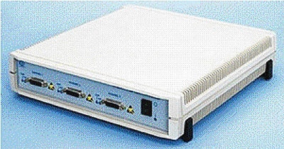
- Stand alone system with universal input power supplies
- State of the art digital signal processor technology, providing sophisticated reconfigurable control parameters.
- 1, 2 and 3 channel systems
- 21 bit effective resolution;
- 7 digit floating-point commands (better than one part in 2 million, equivalent to 0.05 nm in 100 μm).
- Better than 0.02% linearity error
- Snapshot mode allows noise, frequency response and settle times to be graphically displayed on your PC and optimized by adjusting PID loop parameters
- Virtual front panel software allows the user full control of system parameters
- Comprehensive command language DLL allowing simple integration of the system into application specific environments
- Built in RS232 interface allows control from any PC via the serial (COM) port at up to 100 commands per second
- DSP serial port available as standard for high speed communications
- Electronic Data Sheets stored in EEPROM in both the controller and the NanoMechanism allow easy interchangeability of stages and controllers with factory default configuration
- Store and Recall facility for different user setups
Options
- Low noise drift option
- Low drift option
- Analog Interface card (-ANA-A) providing an analog command input for all 3 controller channels
- Parallel Digital I/O card (-PAR-A, -PAR-B or –PAR-C) for high speed communications to a PC based Digital I/O card
- Master / Slave interface cable allowing two NPS3000-series controllers to be controlled from one PC interface (RS232 or Parallel)
Background
The new NPS3000-series digital controllers are completely digital in operation, apart from the input and output amplifiers. This results in lower costs, higher performance and increased flexibility of operation. There are no knobs or switches - everything is set in software, and can be adjusted via a PC using the virtual front panel software supplied. For simple set ups, where speed is not important, or for changing the configuration of the system, then the serial COM port can be used. Where faster operation is required then the fast parallel interface (NPS-PAR) should be specified. Digital interfaces should be used wherever possible, since they do not introduce noise, drift or nonlinearity. In those cases where this is not possible then the analog interface (NPS-ANA) should be used. This is a three-channel A/D convertor board which converts your analog input signal into a digital command.
The NPS3000 series will control any of Queensgate's range of NanoMechanisms, or combinations of piezos and NanoSensors®.
The Queensgate NanoControl Panel
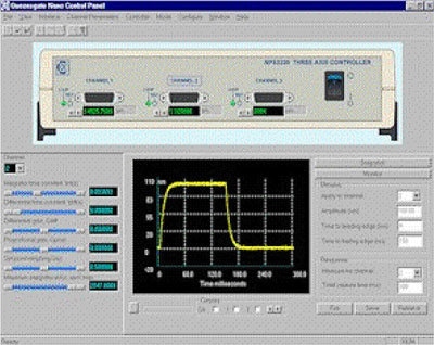
The Queensgate NanoControl Panel provides easy access to the NPS3000 command set. A picture of the controller's front panel, complete with live display of the stage positions and status LEDs, presents an intuitive means of setting up and monitoring the controller. Access to PID parameters is via slider bars; simply move a slider and the corresponding PID parameter will be instantly updated. Other parameters are grouped logically according to function. Changing a command parameter is simplicity itself: just enter the new value and click the mouse.
The Queensgate NanoControl Panel also allows the complete set of command parameters to be saved to disk. This can be retrieved and downloaded to the controller in a matter of seconds. There is no limit to the number of parameter sets that can be stored to disk. The image below is a screenshot of the NanoControl Panel software.
Snapshot Mode
The snapshot mode of operation allows NanoMechanism responses and noise data to be recorded by the controller at the full system cycle rate (one sample every 40ìs), for a limited period of time. This data can then be loaded to the host computer for display and analysis. The snapshot mode can be set up to generate a stimulus on any one of the 3 channels. This means that the response does not necessarily have to be measured for the same channel as that to which the stimulus is applied, and therefore allows inter-channel effects to be characterised.
The NanoControl Panel displays snapshot images alongside the PID slider bars making it easy to adjust the settings and see the change in dynamic performance almost in real time. On-screen cursors are provided to allow measurements to be made directly from the snapshot graph. Snapshot data can also be exported to disk for use with other packages such as a spreadsheet.
Dynamic-Link Libraries (DLLs)
The NPS3000 command DLL provides the link between your Windows programming environment and the NPS3000 controller. It supports the entire command set, allowing you to control and monitor the controller through a series of easy-to-use function calls. The DLL supports both the RS232 serial interface and the NPS-PAR parallel interface. All you need to do is call the appropriate functions; the DLL takes care of the communications.
Software Command Language
The controller command language is largely independent of the communications interface used, although there are some minor differences in the way the commands are transmitted. All transmissions between the host computer and controller (and vice versa) are 64 bits in length, providing fast communications, decode and response times. These comprise a 16-bit command word (or response word), a 32-bit data word and a 16-bit terminator. The data word can contain floating-point or integer format data, depending on the parameter concerned. Command and measured positions can be transmitted in either floating-point or integer format. For floating-point transfers, a choice of IEEE single-precision or TMS320C3X single-precision formats is provided.
The command set includes the following functional groups:
- Control loop mode (open/closed loop; freeze facility.
- Command and measure positions
- PID control parameters
- Linearisation coefficients
- Calibration parameters
- Snapshot settings
- General controller settings
LabVIEW® Drivers
Software support for the NPS3000 series controllers includes a set of Virtual Instruments (VI) drivers for LabView. This means that you can develop your test application working entirely in LabView's 'G' graphical programming environment, so you don't have to write a line of code. It also means that you have a wider choice of platform, including Windows 3.1/95/NT, Sun, Macintosh and HP-UX.
Interfaces
The NPS3000 controllers support the following interfaces:
- RS232 serial interface
- Parallel interface
- DSP port
- Analog interface
- Custom interfaces
RS232 Serial Interface
- Can be used with the standard serial (COM) port on a PC
- Supports 1200, 2400, 4800, 9600, 19200 and 38400 baud (38400 baud may not be supported on some PCs)
Parallel Interface
- Requires the NPS-PAR interface to be fitted into the controller. The NPS-PAR interfaces to a PC via National Instruments PC-DIO-24 Digital I/O Board (desktop PCs) or DAQCard-DIO-24 Digital I/O Card (notebook PCs) and allows command rates of up to 4000 commands per second
DSP Port
- High-speed interface used for communicating between Master and Slave controllers
- Can also be used as the control interface for a stand-alone controller
- Uses Texas Instruments TMS320C32 DSP serial port
- Allows command rates of up to 4000 commands per second
Analog Interface
- Requires NPS-ANA interface to be fitted into the controller
- Provides analog command input for each of the 3 controller channels
- Analog command inputs can be summed with digital command inputs
Custom Interfaces
- Allow command rates of up to 4000 commands per second
- Can be custom designed by Queensgate to meet your requirements
Low Noise (-LN)
- Noise level 3 times lower than standard
- Not available with cables longer than 2m
- Equivalent to 21 bit resolution at 1Hz bandwidth
Low Drift (-LD)
- Drift level of 70 ppm/K in sensor gap
- 3 times lower drift than standard
PID Loop
The controllers use a PID algorithm (Proportional, Integral and Differential feedback terms) to provide flexible control of a variety of stages. This enables rapid settling time to be achieved, minimizing overshoot or ringing and thus allowing the stage to be servo controlled closer to mechanical resonance than would otherwise be possible.
Electronic Data Sheet
Electronic Data Sheets (EDS) are stored in EEPROM in both the controller and the NanoMechanisms, allowing calibration data and dynamic setups to be saved. The NanoMechanism EDS is factory-programmed and includes the following information:
- Stage ID, including Part Number, Serial Number, Manufacture Date and Calibration Date
- Calibration data, including sensor and actuator scale factors Linearisation coefficients.
- Dynamic setup data including PID parameters, ready limit and initial command position. The NanoMechanism EDS has three dynamic setups, which are pre-programmed for slow, medium and fast response times (equivalently large, medium and small loads).
- The NanoMechanism EDS is read into the controller at switch-on, allowing interchangeability of stages between channels and controllers.
- The controller EDS provides storage for the same information described above, for each of the three channels. Thus it is possible to store configuration data even if you are using mechanisms that don't have integral EDS EEPROMS. In addition, the controller EDS provides for five user-defined dynamic setups. You can also specify which dynamic setup (3 factory + 5 user) you wish to be the default setup at switch-on. The controller EDS includes the hardware and the software identification information and the default snapshot settings.
Linearity Compensation
Capacitance sensors, driven appropriately, are inherently linear. However edge effects and manufacturing errors can give rise to non linearity at the 0.2% level. A fourth order polynomial linearization function is applied to the position information before use to reduce this to a negligible level, typically less than 0.02% in practice.
Rotational Error Compensation
The NPS3000 controller has the facility to correct Abbé error introduced by working off axis (away from the defined axis of motion of the NanoMechanism). The rotational errors are calibrated and supplied with each stage. To compensate the Abbé error, the user enters the off axis distance in meters and the magnitude of the rotational error (radians per meter) for the relevant axis. These features can be accessed from the supplied software or called from the Windows DLL or LabVIEW driver.
Specification For NPS3000 Series Digital Controller
|
|
|
Size
|
|
288 x 307 x 70
|
mm
|
|
|
Line Voltage
|
|
90
|
-
|
260
|
V
|
|
|
Line Frequency
|
|
45
|
-
|
65
|
Hz
|
|
|
Stage to controller cable length
|
|
-
|
2
|
10
|
m
|
Note 1.
|
|
Control interface
|
|
RS232
|
|
Note 2.
|
|
Command format
|
|
Single precision floating point (7 digits)
|
|
Note 3.
|
|
Measurement format
|
|
Single precision floating point (7 digits)
|
|
Note 3.
|
|
Scale factor
|
Ax1, bx1
|
|
1
|
|
μm
|
Note 4.
|
|
NanoSensor bandwidth
|
|
|
|
5
|
KHz
|
Note 5.
|
|
Intrinsic noise
|
sensor
|
kxm·ndens
|
|
100 x 10-9
|
|
Hz-½
|
Note 6.
|
|
HV amplifier output swing
|
|
-20
|
-
|
100
|
V
|
|
|
HV amplifier bandwidth
|
|
|
|
10
|
KHz
|
Note 7.
|
|
Intrinsic HV noise (rms)
|
|
|
0.3
|
|
MV
|
|
|
HV amplifier current limit
|
|
|
|
50
|
MA
|
Note 8.
|
|
Warm up time
|
|
|
25
|
|
Minutes
|
|
|
Warm up drift
|
|
|
50
|
|
Nm
|
|
|
Thermal Drift - LD Option
|
|
|
200 x 10-6 70 x 10-6
|
|
K-1
|
Note 9.
|
|
Operating temperature
|
|
0
|
-
|
40
|
C
|
Note 10.
|
|
Survival temperature
|
|
-20
|
-
|
70
|
C
|
Note 10.
|
|
Number of independent closed loop channels
|
|
1
|
3
|
6
|
|
Note 11.
|
| |
|
|
|
|
|
|
|
- 2 m maximum for low noise option (-LN).
- Included as Standard. Other interfaces are available.
- The digital resolution is better than the system noise in most cases. Integer format is also available. The format is user controllable, factory default is IEEE standard format.
- Factory default, User settable.
- The ‘Read Position’ command returns position information in a 5 kHz bandwidth. The ‘Snapshot’ mode returns position information in a 12.5 kHz bandwidth.
- This is the noise for the low noise option (-LN). The standard noise is three times higher. Multiply this number by the square of the sensor gap and the square root of the bandwidth, then divide by the sensor gap for 10 pF capacitance to arrive at the rms noise in meters; that is, noise = kxm·ndens x G2 ¸ d10pF where G is the capacitor gap and d10pF is the capacitor gap for a 10pF capacitance.
- The bandwidth for 4 μF load. The bandwidth at higher loads is 6.1 kHz (6 μF load), 3.7 kHz (10μF load). Typical stage capacitance is 4μF.
- 100 mA current limit is available with less than one minute short circuit protection.
- For example a positioner with a sensor gap of 100 μm with the –LD option has a thermal drift of 7 nmK-1. Note that this is the contribution from the controller only; it does not include thermal expansion of the NanoMechanism.
- Non condensing.
- To obtain six channels two controllers are linked together. Channels can be open or closed loop (user settable).
|