|
Research on new materials technology is attracting the attention of studies all over the world. Developments are being made to improve the properties of the materials and also to find alternative precursors that can bestow desirable properties on materials. Great interest has recently developed in the area of nanostructured carbon materials. Carbon nanostructures are becoming of considerable commercial importance with interest growing increasingly rapidly over the decade or so since the discovery of buckminsterfullerene, carbon nanotubes, and carbon nanofibers.
Carbon Nanotubes
Carbon nanotubes (CNTs) exhibit unique mechanical, electronic and magnetic properties, which have caused them to be widely studied [1-3]. CNTs are probably the strongest substances that will ever exist with a tensile strength greater than steel, but only one sixth the weight of steel [4]. Iijima (1991) first discovered carbon nanotubes (CNTs) using arc discharge method [5,6]. Following this discovery, a number of scientific research projects have been initiated and a variety of methods have been used to synthesize CNTs, namely, arc discharge, laser vaporization [7] and catalytic chemical vapor deposition of hydrocarbons [8-10]. Since carbon–carbon covalent bonds are one of the strongest in nature, a structure based on a perfect arrangement of these bonds oriented along the axis of nanotubes would produce an exceedingly strong material. Nanotubes are strong and resilient structures that can be bent and stretched into shapes without catastrophic structural failure in the nanotube [11, 12]. The Young's modulus and tensile strength rival that of diamond (1 Tera Pascal and ~200 Giga Pascal, respectively) [13].
Carbon Nanotubes as Reinforcements in Composite Materials
This fantastic property of mechanical strength allows these structures to be used as possible reinforcing materials. Just like current carbon fiber technology, these nanotubes reinforce would allow very strong and light materials to be produced. These properties of CNTs attracted the attention of scientists in all over the world because their high ability for absorbing the load which is applied to nanocomposite materials [11-13].
Multi-Walled Carbon Nanotube-Based Nanocomposites in This Study
Multi-walled carbon nanotubes (MWNTs) will be used to prepare natural rubber (NR) nanocomposites. Our first effort to achieve nanostructures in MWNTs/NR nanocomposites will be formed by incorporating nanotubes in a polymer solution and subsequently evaporating the solvent. Using this technique, nanotubes will be dispersed homogeneously in the NR matrix in an attempt to increase the mechanical properties of these nanocomposites. The properties of the composites such as tensile strength, tensile modulus and elongation at break were studied.
Experimental
The FC-CVD reactor has been designed to produce CNF & CNT. The production of carbon nanofibers/ nanotube in the present work has been conducted in a horizontal tubular reactor. The horizontal reactor is a quartz tube of 50 mm in diameter and 900 mm in length, heated by silicon carbide heating element. Two conical flasks connected to each other with an insulated plastic tube, one of them for the hydrocarbon source and the other one for the catalyst source were placed before the tubular reactor. They were connected to the reactor through a stainless steal pipe. The flask, which contains the catalyst, was placed on a heating mantel with a temperature controller. Two types of gases were used in this system, hydrogen was used as a reacting gas and the argon for flashing the air from the system, and both of them were controlled by a flow meter. One condenser was placed after the reactor to cool down the gas outlet temperature and entrapped materials as shown in the schematic diagrams and picture in figure 1.
|
|
|
Figure 1. Schematic diagram of modified FC-CVD.
|
The carbon nanotubes were added to natural rubber as a filler. The natural rubber, which was used in this study, is a Standard Malaysian Rubber Constant Viscosity 60 (SMR CV 60). The preparation of the nanocomposites was carried out by using a solvent casting method using toluene as a solvent. The added amounts of the carbon nanotubes were 1, 3, 5, 7 and 10 wt % of 10 grams of the total weight.
The process of making natural rubber/nanotubes as nanompcosite material divided into the four following processes.
Dispersion of Nanotubes
This phase involves the dissolution/dispersion of CNTs in a solvent (in this case, toluene) in order to disentangle the nanotubes that typically tend to cling together and form lumps, which become very difficult to process. For this, a certain quantity of carbon nanotubes or nanofibers was added to a specific amount of toluene solution after carefully weighing (in order to maintain a specific weight ratio of nanotubes in the solution). This solution was further sonicated using a mechanical probe sonicator (Branson sonifier), capable of vibrating at ultrasonic frequencies in order to induce an efficient dispersion of nanotubes or nanofibers. For this study, different CNT solutions were prepared (containing CNTs in various weight ratios):
i) 1 wt% CNTs containing in 10ml of toluene solution
ii) 3 wt% CNTs in 10ml of toluene solution
iii) 5 wt% of CNTs in 10ml of toluene solution
iv) 7 wt% CNTs in 10ml of toluene solution
v) 10 wt % CNTs in 10ml of toluene solution.
Dissolution of the Rubber
This stage involves the dissolution of the Rubber in a suitable organic solvent (toluene). A specific amount of rubber (in this case, 10 gms) weighed using a balance was added to a certain quantity of organic solvent (500 ml of toluene) thereby maintaining a desired rubber weight ratio. This mixture was stirred and kept for certain duration of time until the rubber became uniformly dissolved in the solvent.
Mixing of Rubber with Nanotube Solution
This is the final step in the melt preparation process and basically involves thorough mixing of the solutions prepared in the first and second stages, resulting in a solution that consists of a good blend of nanotubes in the rubber.
Pressing and Testing The Sample
The nancomposite material (rubber with CNTs) was pressed using hot press and cut into standard shapes. The samples were then characterized and mechanical properties measured.
Results and Discussion
Production of Multi Wall Carbon Nanotubes (MWCNTs)
In this research work, MWCNTs were produced by using floating catalyst chemical vapor deposition (FC-CVD). To produce these carbon materials, carbon atoms bond together in the presence of iron (Fe) catalyst.
The iron (Fe) catalyst, in particle form was obtained from decomposition of the ferrocene. The carbon atoms produced from the cracking of benzene C6H6 served as the raw materials. The product was collected from the wall of the reactor and the ceramic boats, which were placed at the center of the reaction chamber. The study of the effects of each key parameter on the yield, purity, average diameter and distribution of the carbon material are discussed, however greater emphasis were placed on CNTs and to a lesser extent CNFs because of their industrial importance and wider applicability. The production conditions of pure CNTs have been fixed at reaction temperature 850°C, hydrogen flow rate 300 ml/min and reaction time 45min. The diameters of the CNTs were varied from 2 nm to 30 nm and the average length was at 70 µm.
SEM Characterization
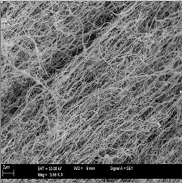
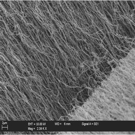
The resultant carbon nanotubes were characterized extensively using SEM. Figure 1 shows typical SEM images of carbon nanotubes. High purity, carbon nanotube array were observed in figure 1. The SEM observation shows that these carbon nanotubes are tens of microns long (up to 50 micron) with uniform diameters. The bulk morphology of the long carbon nanotubes are film like and oriented. However, the images indicate that the products are clean except for some nanoparticle impurities.
|
|
|
Figure 2. SEM Images of carbon nanotubes reaction temperature 850°C, hydrogen flow rate 300 ml/min and reaction time 45min.
|
TEM Characterization
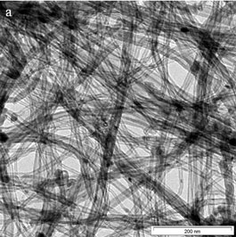
TEM was carried out to characterize the structure of nanotubes (Figure 2). To prepare TEM samples, some alcohol was dropped on the nanotubes film, then, these films were transferred with a pair of tweezers to a carbon-coated copper grid.
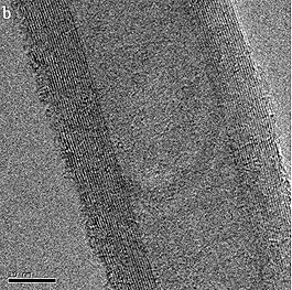
The TEM images of nanotubes are presented in figure 3(a). It is obvious, from the images that all the nanotubes are hollow and tubular in shape. In some of the images, catalyst particles can be seen inside the nanotubes. TEM images indicate that the nanotubes are high purity, with uniform diameter distribution and contain no deformity in the structure. While figure 3(b) shows the High Resolution Transmission Electron Microscope (HRTEM) of the carbon nanotubes. It shows that a highly ordered crystalline structure of CNT is present. The clear fringes of graphitic sheets are well separated by 0.34 nm and aligned with a tilted angle of about 2° toward the tube axis.
|
|
|
Figure 3. TEM images of CNTs (a) Low resolution (b) High resolution.
|
Carbon Nanotube/Natural Rubber Nanocomposites
In this research work, carbon nanotubes were employed as an interface nano-reinforcement in an advanced commercial carbon/rubber composite and this is the first time such work has been reported. Theoretical predictions of the mechanical properties of carbon nanotubes as described above, in particular their predicted high strengths (of the order of 60 GPa) and modules (~1 TPa), make them attractive candidates as a reinforcement filler material in polymer based structural composites. Initial experimental work on carbon nanotube-reinforced CNT-NR has demonstrated that large increase in effective modulus and strength can be obtained with the addition of small amounts of carbon nanotubes.
TEM Observations
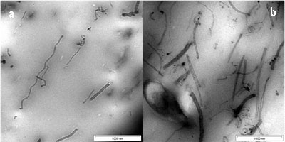
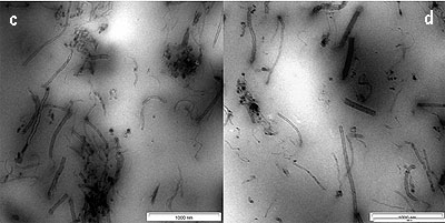
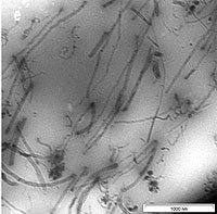
The dispersion of CNTs in the SMR CV60 was characterized by using Transmission Electron Microscopy (TEM). A thin section of about 100 nm was cut with a diamond knife at -120°C to observe the dispersion of CNTs inside the rubber. In figure, 4(a) short and long CNTs are seen. It was shown in this figure that the CNTs are homogenously distributed in the SMR CV60 matrix. However, the CNTs are open at both ends during the dispersion of the CNTs into the toluene, using ultrasonic frequency vibration and during the mixing of CNTs in the SMR CV60 by mechanical stirring. The distance between the CNTs in the matrix is wide and that makes them well oriented with little interface interaction between them. The size of the CNTs in the TEM shows varying diameter from 2-20nm and varying length, which can be either short or long. Figure 4(b) shows the image of a 3 wt % CNTs, dispersed in the matrix, the orientations of the CNTs in the SMR CV60 had become less oriented and more random. The figure also shows that the CNTs are open at the end. Figure 4(c, d and e) shows the CNTs in the SMR CV 60 at 5, 7, and 10 wt % respectively. The figures also indicate that the orientation of the CNTs plays a very important role in the stress and strain of the matrix. Another factor considered important on the mechanical properties is the aspect ratio; if the aspect ratio is high the strength of the material will increase.
|
|
|
Figure 4. TEM image of CNTs in SMR CV60 (a) 1 wt % of CNTs (b) 3 wt % of CNTs (c) 5 wt % of CNTs (d) 7 wt % of CNTs and (e) 10 wt % of CNTs.
|
The stress-strain curve of different percentages of pure carbon nanotube (1, 3, 5, 7 and 10 wt % of CNTs) with SMR CV60 is presented in figure 5. The tensile strength radically increases as the amount of CNTs concentration increases. The general tendency is that the stress level is increased by the addition of CNTs which plays the role of reinforcement. From these results, it is deduced that the reinforcing effect of CNTs is very marked. As the CNT content in the rubber increases, the stress level gradually increases but at the same time the strain of the nanocomposites decreases.
|
|
|
Figure 5. Stress-strain of SMR CV60 with different percentage of CNTs.
|
The increased level of stress was due to the interaction between the CNTs and the rubber. A good interface between the CNTs and the rubber is very important for a material to withstand the stress. As described above CNTs are extremely strong materials compared to other types of fillers, thus making them good candidates as nanofillers. Under load, the matrix distributes the force to the CNTs which carry most of the applied load.
Effect of CNTs on the Young’s modulus of SMR CV 60.
The same phenomenon was observed for Young’s Modulus. The young’s modulus of the composites normalized with that of the pure matrix is presented in figure 6. The result indicated that the Youngs Modulus increased with an increase in the amount of the CNTs in the formulation. However, at 1 and 3 wt % of CNTs, the increment of the modulus is not as high as that of the tensile strength. The same value of the modulus and the tensile strength were observed at 5 wt % of CNTs. While at 7 and 10 wt % the modulus was higher than the tensile strength.
|
|
|
Figure 6. Young Modulus of SMR CV60 at different percentage of CNTs.
|
Effect of CNTs on the Energy Absorption of SMR CV 60
Figures 7 shows the toughness of the nanocomposite and considers the amount of energy required to fracture a material. The figure shows that, by increasing the amount of CNTs into the SMR CV60 the energy of absorption needed to fracture the material increases. Since strength is proportional to the force needed to break the sample, and strain is measured in units of distance (i.e., the distance the sample is stretched), then strength times strain is proportional to force times distance which in turn equals to energy i.e.:
Strength × strain ~ force × distance = energy
|