Advances in the technology and medical sector are heavily depending on faster, smaller and smarter precision motion control and positioning equipment. Design engineers now have access to a growing spectrum of options to improve production processes with new types of nano-precision mechanisms, and novel position sensing and force feedback technologies. Applications include mission-critical deployments in laser micro-machining, micro-assembly automation, optical inspection, semiconductor metrology, photonics components test & alignment applications to name a few.
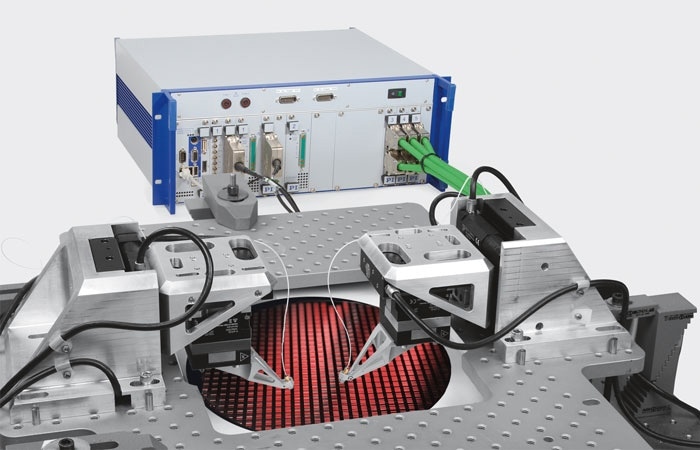
Silicon Photonics (SiP), the convergence of photonics and semiconductors promises a leap in data throughput, parallelism and energy efficiency. Wafer level testing and packaging economics both demand extraordinary speed and parallelism. This is achieved by a combination of motorized and piezoelectric drive technologies along with high-speed, firmware-based search and align algorithms. (Image PI)
A similar feedback loop of application-demand-and-industry-response animates the laboratory research market, where rapidly advancing scientific endeavors demand ever finer and faster control of motion. Here, we see advanced motion technologies at the foundation of current Nobel-winning super-resolution microscopies, single-molecule biophysics investigations, and the latest photonics and materials developments.
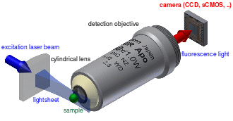
Digital light sheet microscopy can provide time resolved 3D images of biological processes, critical for progress in neuroscience research. In addition to lasers and optics, it relies on several advanced precision positioning technologies. (Image: Wikipedia)
Today’s broadening spectrum of research and industrial applications has yielded a similarly wide range of motion technologies — more than a single article can review comprehensively. But it means that Motion Control Engineers and Designers in scores of industries have access to precision motorized positioning systems that fit or even enable their applications. These systems provide extremely few limitations on travel, repeatability, precision and speed. Following is an overview of the more well-known types of motorized precision-positioning systems and some of their news.
Precision Linear Actuators
A precision linear actuator is defined as a positioning device that produces motion in one degree of freedom, and usually does not include a guiding system for the payload. This discussion focuses on electrically-driven units, though, of course, manual micrometer-driven are common, along with screw-driven, hydraulic and pneumatic variants for lower-precision applications. A number of drive technologies are capable of producing linear motion:
Electro-Mechanical Actuators
These are normally based on linear shafts driven by rotational electromagnetic motors via ballscrews or lead screws. Rotary motion of the motor is transformed to linear displacement. The actuators have a generally cylindrical format. Small versions are used to replace precision screws or micrometers, conferring automated actuation.
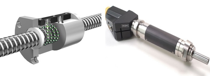
(left) Basic design of a recirculating ballscrew. (Image: THK)
(right) A stepper motor driven ballscrew precision actuator, capable of sub-micrometer precise motion and high push/pull forces. (Image: PI miCos)
The motors used in these actuators are typically either DC servomotors or stepper motors. Stepper motors actuate a toothed rotor within a toothed, surrounding stator. The permanent magnet stepper motor, which is the most common type, employs a rotor made up of a magnetized material. By configuring the magnetic windings of the stator so that groups of its teeth can be specifically magnetized, the rotor is caused to rotate in steps. It will hold position at these full step positions without power. Partial steps can be attained by partly energizing the windings. As a result, a driving mode that produces “micro” or “mini” steps can be implemented, multiplying the stepping resolution of the motor.
Basic operating principle of a stepper motor. (Image: Wikipedia)
DC servo motors are considered to be conceptually simple: a magnetized rotor within a magnetized stator, both of which have a South and a North pole. The poles of each are repelled by or attracted to each other, causing rotation to an equilibrium orientation, just as a compass is caused to orient itself with the Earth’s magnetic poles. By varying the magnetization of the stator or rotor or both electromagnetically, such as switching their polarities by using a brushed or electronic commutation approach, it is possible to make the motor spin freely and, with the addition of a position feedback encoder, provide precise positioning with excellent responsiveness. Brushless DC motors, with electronic commutation instead of commutation via carbon brushes, provide improved lifetime, especially in high-dynamic applications and can be used to offer a high static torque without problems.
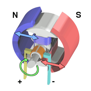
A simple brushed DC servo motor. (Image: Wikipedia)
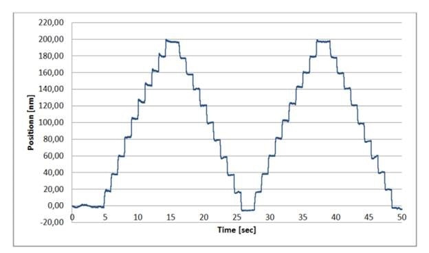
20 nm steps of an L-511 linear translation stage with stepper motor / ballscrew drive measured on an interferometer. The 200 full-step motor was controlled by a SMC Hydra controller running in microstep mode (3000 microsteps/fullstep). (Image: PI)
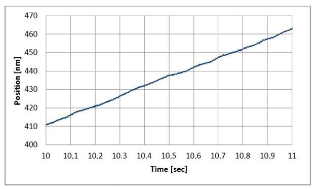
Constant velocity of an L-511 linear translation stage, commanded at 50 nm/sec, controlled by a SMC Hydra controller in 3000 microstep mode. Driven in with a good microstep controller, stepper motor stages can provide exceptionally smooth motion. (Image: PI)
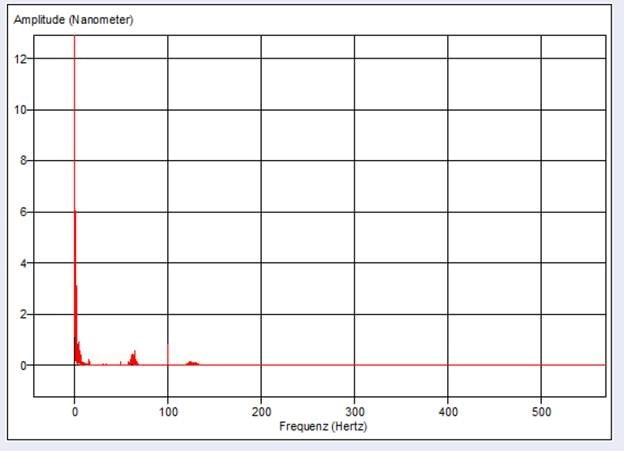
Extremely smooth motion and absence of vibration is shown in the FFT analysis of the position deviation of an L-511 stepper motor stage moving with constant velocity at 5µm/sec. (Image: PI)
Stepper motors can be operated closed or open loop, meaning with or without position feedback. It is possible to actuate a stepper motor through any specified number of steps in either direction and offers a high probability of attaining them, though certainty can only be obtained by the inclusion of a position encoder. Rotary encoders keep track of the position of the rotating motor; linear encoders encode the output position of the driven linear shaft directly, thus eliminating backlash and various other errors that could otherwise build up in the drivetrain where a rotary encoder cannot observe them. Though linear actuators with linear encoders are uncommon, they still offer unbeatable bi-directional repeatability for sensitive applications.
Piezoelectric Actuators
Extremely fine positioning resolution can be achieved by piezoelectric actuators. There are several types:
Piezo stack actuators are exquisite, layered structures of specialized ceramic interleaved with metallic electrodes. The piezo ceramic has the exceptional property of expanding in a controllable manner by applying an electrical field. These actuators provide short travel ranges (about 1% of their length), high forces, sub-nanometer precisions and sub-millisecond response. These are considered to be the mainstay of today’s enhanced nanotech applications, both in industrial applications and laboratory research, such as genomic sequencing and semiconductor manufacturing. Piezo stack actuators are inherently solid state, non-magnetic and vacuum-friendly, with no wear processes.
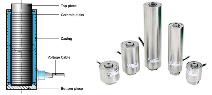
(left) Basic design of a piezo stack actuator: A number of thin electro-ceramic layers expand when energized. Micro-second response, high forces, and ultra-high precision are achieved. (Image: PI)
(right) P-235 high-force piezo linear actuators. These actuators can position loads of several tons with nanometer precision. (Image: PI)
Piezo stack actuators can be incorporated in flexure guiding systems with motion amplifiers in order to provide longer travel ranges and multi-axis motion if needed. Wire EDM cut flexures provide modern guiding precision together with virtually friction free motion and zero wear and maintenance. NASA achieved 100 billion cycles of motion without failures during life testing for the Mars Mission.
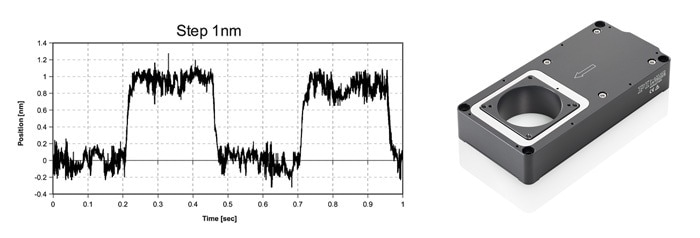
Piezo positioners can resolve motion down to 1/10 nanometer and below. The above graph shows the crisp step and settle performance of a P-630 linear stage commanded to move 1nm increments, measured with an external laser interferometer.
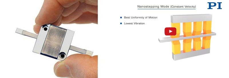
Ultrasonic piezomotors are monolithic piezo ceramic structures that are stimulated at their resonant frequency, normally above 100 kHz, resulting in them fluttering on a submicron scale. A friction tip developed or bonded at a resonant node conveys this fluttering oscillation to a workpiece that rides in bearings. The workpiece thus experiences a force that drives it one direction or the other. These motors are capable of attaining many millimeters of travel and extraordinary speeds in an extremely small package. For example, PI’s patented PILine® ultrasonic piezomotors can provide speeds to half a meter per second and settle/step times of a few milliseconds in some applications. Another chief attribute refers to the automatic self-locking behavior of these motors when at rest and even when unpowered. This prevents drift and dither of the driven stage. Ultrasonic piezomotors have the potential to provide an application-enabling alternative to classical motors when high speed, small dimensions and unrivaled energy efficiency are vital. Similar to piezo stack actuators, ultrasonic piezomotors are vacuum-compatible and non-magnetic.
Ultrasonic motor high-speed actuator for OEMs (Image: PI)
Ultrasonic Motor Operating Principle PILine Linear / Rotary Piezo Motor by www.pi.ws
Video - Working principle of ultrasonic linear and rotary motors (Image: PI)
Inertia drives, another type of piezomotor, use tiny piezo ceramic elements that are actuated in a sawtooth pattern, driving a shaft or other actuated element through a friction coupling. In fact, it is the sloped portion of the sawtooth actuation that provides the motion; the rapid retraction breaks the stiction of the coupling and the actuated element does not retract with the piezo ceramic element. Artful design can acquire silent, virtually stepless operation and long travels along with precision to the nanoscale and self-locking for high stability when stationary. Examples include PI’s U-Motion series of ultra-compact open and closed loop stages, and PIShift actuators.
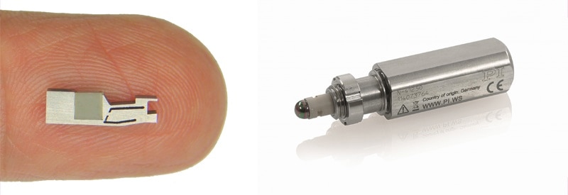
(left) Piezo inertia motors are tiny. They provide nanometer precision and are ideal for integration into miniaturized instrumentation. (Image: PI)
(right) A linear actuator based on a high-force stick-slip inertia motor. (Image: PI)
Piezo ratchet motors are considered to be a special form of inertia motors based on the stick-slip effect. A precision lead screw is driven by a small piezo ceramic actuator embedded in a spring-loaded mechanism. A slow expansion phase results in a small rotation of the screw. When the piezo element has reached, its maximum expansion, a much shorter contraction phase follows – extremely fast for the screw to follow due to its inertia.
Closed and open loop operation is possible. An optical encoder integrated into the actuator housing feeds the information back to a closed loop controller when exact position control is needed. Resolution in the nanometer rage is feasible. Advantages include the self-locking design, compact size and high holding forces (100N) compared to the size. Drawbacks refer to the slow speed – making the drive an ideal option for motion control applications in confined spaces with low dynamic requirements – such as alignment of optics, laser tuning, and opto-mechanical equipment, and a great choice for replacing mechanical micrometers.
Closed-Loop Precision Actuators - How does a Piezo Ratchet Mechanism Work?
Animation of N-472 miniature actuator. (Image: PI)
Walking piezomotors are considered to be yet another breed. These use four or more piezoceramic fingers, which actuate in a stepping sequence in order to drive a workpiece in a desired direction. Between steps, sub-nanoscale actuation can be achieved. High power-off holding forces and essentially unlimited travel characterize these designs, exemplified by PI's NEXACT and NEXLINE technologies. The usual non-magnetic and vacuum-friendly attributes apply. These have proven to be enablers in sensitive optical positioning applications where carefully established positions must be maintained with nanometer stability without power for months or years.
A compact actuator based on the PiezoWalk principle. (Image: PI)
Operating Modes of High-Force Piezo-Walk Motor / Drive System, Nanometer Precision
Video - Multiple operating modes of a PiezoWalk linear actuator. (Image: PI)
Linear Motor Actuators
By attaching a linear servo motor (which can be thought of as a rotary DC motor sliced lengthwise and laid flat) to linear guidance and an output shaft, direct linear actuation of extremely high speeds can be achieved. Linear DC motors can have a multitude of North/South magnetic pairs, based on how much travel is required. These serve the role of the stator in a rotary motor. Gliding along them to produce force is a three-phase coil assembly. The phases are electronically commutated in order to produce smooth motion in the desired direction, ensuring long life.
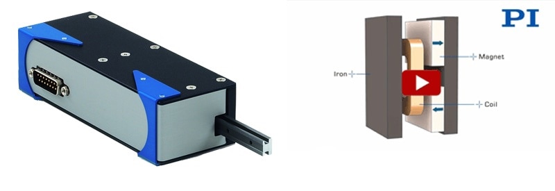
A voice-coil-driven linear actuator for closed-loop position and force control applications. Advantages are fast acceleration, high speed, and long life. (Image: PI)
How Does a Voice Coil Motor Work - Applications in Linear Actuators and Linear Stages. By www.pi.ws
Video - Physics behind a voice coil drive. (Image: PI)
A related type of linear actuator is driven by a voice coil motor, which refers to a nested pair of cylindrical electromagnetic coils capable of attracting or repelling each other along their mutual axis. These provide travels on the order of 25 mm and provide extraordinary speeds and accelerations for small loads. Such mechanisms are extremely long lived. Voice coil actuators, like PI’s V-270 series, can offer impressive step/settle times due to their high responsiveness, and their direct actuation of the motion shaft in its low-friction bearings provides exquisite force control as well when an optional tip-force sensor is integrated. The sophisticated industrial digital controller of V-270 series actuators offers bumpless switching between a wide range of position, force, velocity and mixed servo modes, which makes them suitable for production applications including testing of touch-sensitive devices and calibrated force generation.
Linear Translation Stages
A linear or translation stage builds on the principles of a linear actuator, but adds a workpiece or platform for fixing an application load, or for stacking extra stages to form a multi-axis configuration. The stage’s workpiece is a precision component with a linear bearing for guidance.
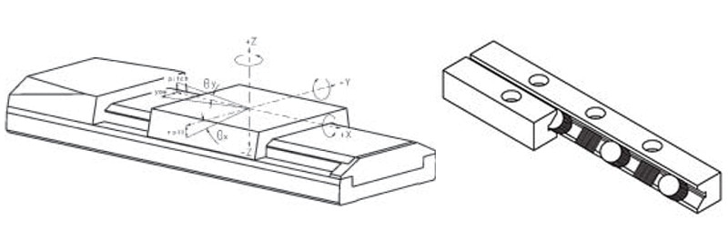
(left) Ideally, a linear translation stage should only provide motion in one degree of freedom. In reality, there is no perfect guiding system, and every linear motion will also bring about rotary / tilt errors (angular deviation) and motion components in two unwanted linear degrees of freedom (runout). (Image: PI)
(right) Crossed roller bearings provide high load capacity and better guiding precision than most ball bearings. (Image: PI)
A linear translation stage restricts teh application load to a linear single degree of freedom. An ideal linear stage completely restricts two axes of translation and three axes of rotation, thus allowing for motion on only one translational axis. In reality, there is no perfect guiding system, and every linear motion will also bring about tilt/rotary (angular deviation) and motion components in two unwanted linear degrees of freedom (runout). The capability of linear stages to provide high precision linear motion with minimized runout is critical to the success of scientific and industrial applications, such as Semiconductor Manufacturing, Research and Industrial Biotech Instrumentation, Aerospace, Materials Science, Photonics Instrumentation, and Beam Line Instrumentation.
Motorized linear stages comprise of a base and a platform, attached by some form of guide or linear bearing in such a way that the platform is restricted to linear motion with regard to the base. The position of the moving platform relative to the fixed base is normally controlled by a linear actuator of some form. The most common method is to integrate a lead screw or ball screw passing through a lead nut in the platform, as described for linear actuators.
Direct Drive Piezo Motors for Nanopositioning, Delay Line Stages, Nano-Alignment - How do they Work?
How Piezo Walk Motors Work in Linear Stages.
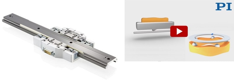
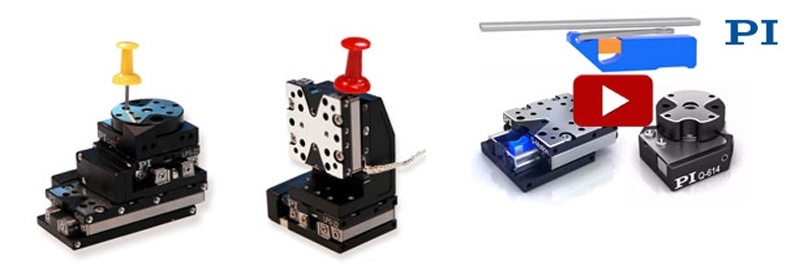
However, as the drive-technology options have expanded, novel linear stages that incorporate the latest drive technologies have been introduced. These yield advantages of importance to specific applications, such as non-magnetic actuation or package-size benefits. For instance, PI’s U-751/M-686 microscopy stage provides both lower and higher speed capabilities when compared to typical stepper-motor microscopy stages, and integrates a linear encoder for 100 nm-scale bi-directional repeatabilities, all without the bulky overhanging lead screw/stepper-motor assembly that projects from the side of each axis of standard microscopy stages.
A low profile XY motor stage for microscopy applications. The ultrasonic ceramic motors are compact and self-clamping, providing extremely good long term stability without position drift. (Image: PI)
Nano-Precision Motion / Positioning for Microscopy & Imaging: What is Available? by www.pi.ws
Video - Ultrasonic-motor drive principle. Ultrasonic motors provide a very large dynamic range from a few nanometers/second to 100’s o mm/second. (Image: PI)
For motion and positioning in multiple axes, individual positioning stages can be combined or parallel-kinematic hexapods with up to 6 degrees of freedom of motion can be used.
Bigger is not Always Better
The requirements for smaller motion systems are driven by the need for miniaturization in the medical device and semiconductor industry. Smaller also means lower mass and the potential for higher acceleration and throughput, particularly when incorporated with the advanced actuation technologies that are presently available.
Linear Positioning Stages with Piezomotors
A new generation of piezo ceramic linear motors enables the construction of matchbox to thumbnail sized linear stages with nanometer resolution and millisecond step/settle times.
The direct drive prevents mechanical components, such as lead screws and gears, making for high-resolution and reliable drives down to a few nanometers. High forces, high velocity, and/or high resolution are achieved based on the drive principle.
Miniature linear positioning stages with linear encoder feedback and high-speed ultrasonic ceramic linear motor are shown below.
Q-motion miniaturized linear and rotary positioners based on the stick-slip effect. Nanometer precision is feasible, the drives are self-clamping when powered-off. (Image: PI)
Miniature Linear Stage | Miniature Rotary Table, Rotation Stage w/Piezo Motor: How it works | PI
Video - Operating principle of stick slip inertia motor. (Image: PI)
Long Travel – Industrial Applications
Some industrial automation processes, such as laser processing and flat panel testing, require extremely long travels past one meter with high speed and low runout errors. Air bearing stages with linear motors are now considered to be the gold standard for these applications.
Air Bearing Linear Stages – Planar XY Stages
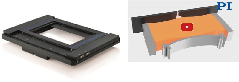
Mechanical bearings are replaced with a frictionless air film by air bearing stages, which also maximize throughput while providing the ultimate level of precision, particularly for multi-axis motion. Planar designs employ one reference base plane on which magnetically or vacuum preloaded pucks are floating for both the Y and X axes. H-bridge, three-motor designs provide the highest precision, and can be further enhanced with active yaw control when provided with three linear encoders and improved motion controllers. The benefit is immensely enhanced orthogonality and straightness. Air bearing stages are generally driven by magnetic linear or torque motors that offer smooth motion without negative cogging effects.
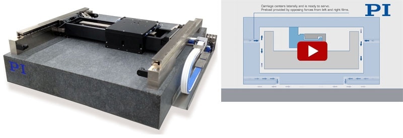
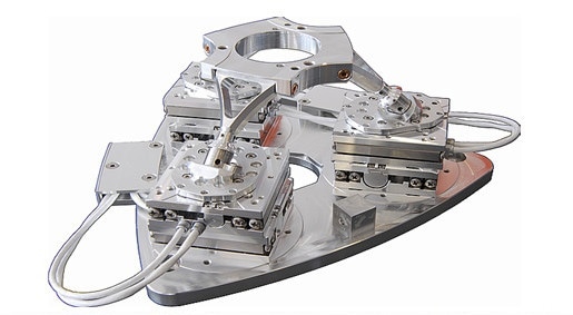
A planar air bearing XY positioning stage with active yaw control for improved straightness of motion. (Image: PI)
Air Bearings How do they work? Example XY Air Bearing Stage, PIglide XY-Table
Video - Operating principle of an air bearing stage. (Image: PI)
High-Speed Stages with Linear/Torque Motor Direct Drive
It is also possible to combine linear and torque motors with mechanical bearings. This combination is frequently used in industrial applications when the smoothness and flatness/straightness of motion is not considered to be as critical as with air bearings. Linear motors offer an outstanding combination of precision, reliability and speed.
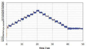
2 nanometer steps performed repeatedly by a V-551.4B stage with absolute encoder (BISS), driven by the C-891 motion controller, measured with Zygo ZMI interferometer. Steps down to 1 nanometer can be resolved with the absolute encoder. For even smaller steps, the PIOne incremental encoder is available.
The high dynamics of linear motors guarantees high throughputs of automated tasks in testing systems, for instance, in the semiconductor industry. They also increase efficiency, for example, in assembly lines/electronics production or laser processing.
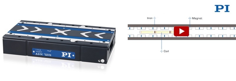
V-551 translation stage with 3-phase linear motor (Image: PI)
Linear Motors - How Does a 3-Phase Motor work in a Linear Motor Slide | Direct Drive Motors
Video - Physics behind a 3-phase motor (Image: PI)
High-Resolution Linear Encoder Feedback
Unlike motion systems that are operated by rotary stepper and servo motors and lower precision rotary encoders, linear motors require linear positional feedback systems. A linear encoder is a digital position transducer that directly measures linear motion where it takes place as opposed to a rotary encoder mounted at the end of a drive train. The actual position is read by the linear encoder as close to the point of interest as possible, and therefore, the resulting accuracy and repeatability of the payload is higher. Linear encoders comprise of a read head and a linear track. The linear track can range in length from a few mm to several feet. While most encoders are based on an optical grating, cost-effective magnetic encoders are still available. While resolution in the sub-nanometer range is common, accuracy is usually limited to 1 µm per 100 mm. However, this can be improved significantly with current controllers if calibrated and compensated for with look up tables or polynomial error correction. Incremental linear encoders are still prevalent, because of their interfacing simplicity and higher possible resolution down to the picometer range if used with electronic interpolators, but absolute position encoders are indeed catching up with nanometer resolution models becoming a lot more affordable.
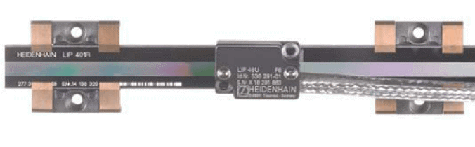
LIP481U linear encoder. (Image: Heidenhain)
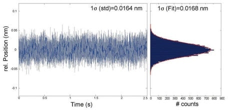
Noise measurement of a positioning system with a PIOne linear encoder (400 kHz bandwidth, 18-bit resolution): 16 picometer RMS and 100 picometer peak-to-peak. (Image: PI)
Rotation Stages
Rotation stages comprise of a platform that rotates relative to a base. The base and platform are joined by some form of bearing which restricts motion of the platform to rotation about a single axis.
A wide range of motors and drive principles can be used, from direct-drive closed loop torque motors to stepper-motor driven worm gear designs. Self-locking capabilities with zero jitter and drift are provided by low profile piezo motor stages, requiring no holding current at rest.
Precision motorized rotation stages are employed in applications such as semiconductor inspection, fiber-optical alignment, X-ray crystallography and bio-medical applications.
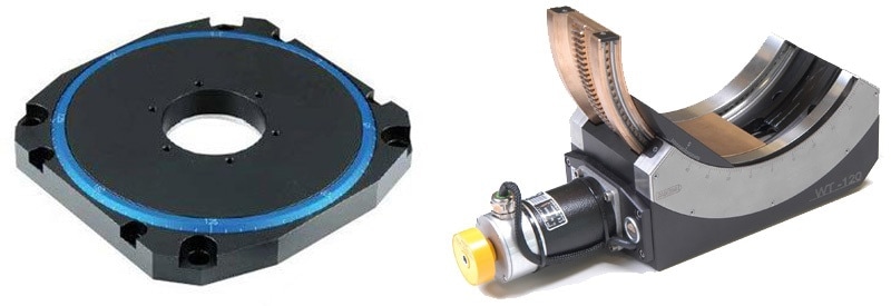
(left) U-651 low profile rotation stage based on ceramic direct-drive motors. (Image: PI)
(right) High precision motorized goniometer cradle. (Image: PI miCos)
Air-Bearing Rotation Stages
Air bearings use a thin film of pressurized air to provide an exceedingly low friction load-bearing interface between surfaces. The two surfaces do not touch. Since they are contact-free, air bearings prevent the traditional bearing-related problems of friction, particulates, wear and lubricant handling, and offer distinct advantages in high-speed and precision positioning applications, where the elimination of static friction and backlash are critical.
Direct-Drive Rotary Table, High Precision Air Bearing Spindles w/ Rotary Torque Motor | PI
Video - Look inside torque-motor driven rotary stage. (Image: PI)
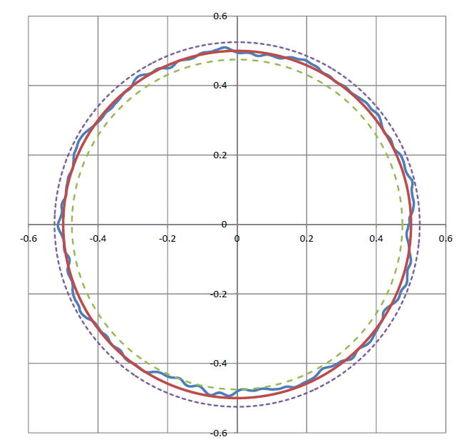
Rotary air bearings stages provide extremely good guiding precision. The graph above shows radial runout error motion of a PI RT300L stage. Red line: perfect circle with no error. Blue line: actual error (in microns). Dashed lines: max/min error bands around the perfect circle. (±25 nanometers) (Image: PI)
Air-bearing rotation stages, generally used for the highest precision and smoothness of motion/velocity, deliver ultra-low runout and wobble, as well as very high resolution and repeatability. Pitch, yaw, roll on the order of one arc second is feasible. The absence of friction prevents backlash and provides the air bearing stage ultra-high repeatability. If calculated, designed and operated correctly, the durability of air bearings is unlimited.
Goniometers
A goniometer is an instrument that either allows an object to be rotated to a precise angular position or measures an angle. A goniometric stage or positioning goniometer is a device used to rotate an object precisely about a fixed axis in space. It is similar to a linear stage, but instead of moving linearly with respect to its base, the stage platform rotates partially about a fixed axis above the mounting surface of the platform. A worm drive with a partial worm wheel attached to the underside of the stage platform meshing with a worm in the base is typically used by positioning goniometers. A motor rotates the worm.
Goniometers are frequently used in X-ray diffraction and in crystallography to rotate the samples. They are also employed in (fiber) optic alignment applications.
6 DOF – Parallel Kinematic Systems: Hexapods/PlanarPods
Hexapod parallel positioners have become popular in the last two decades in order to attain precision at the micron and sub-micron level in multi-axis motion applications. Hexapods effectively decrease the moving mass and footprint of a traditional serial kinematic stacked-stage positioning system while increasing responsiveness and stiffness. This together with a large clear aperture and the arbitrary, user-defined center of rotation make them the positioning system of choice in mission-critical applications, including photonics alignment, laser processing and micro-machining in medical devices and other applications.
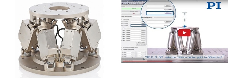
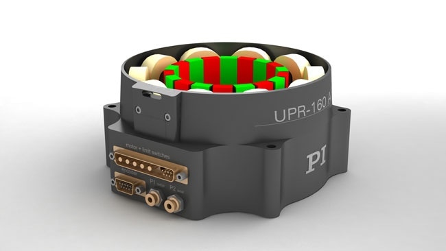
Vacuum compatible hexapod 6-axis positioning system (Image PI)
Fast Programming of 6-DOF Hexapod 6-Axis Motion Stewart Platform: Software, Mechanics, Controller
Video - Hexapod parallel-kinematics approach compared to traditional stacked multi-axis stage (Image: PI)
Hexapods, by definition, are six-legged parallel-kinematic mechanism (PKM) motion systems. In their most common form comprising of two platforms, a second movable platform and a fixed base platform, which are connected and supported by six independent legs (struts or links) that expand and contract in parallel. A similar 6-axis design, known as SpaceFab, is based on a top platform connected to three XY linear stages with three passive struts. It offers similar performance to a hexapod, yet allows for longer XY travel ranges (with reduced angular motion) and a lower profile.
Coordinated motion of all struts enables the movable platform, and devices mounted on it, to move in any direction, working in 6-D relative to the base platform. With 6-DOF, the secondary platform is capable of moving in the three angular directions (roll, pitch and yaw), and three linear directions, lateral (X), longitudinal (Y) and vertically (Z), by the legs. Since hexapods have all six degrees of freedom, they can execute manipulations that encompass total freedom of motion in a relatively compact space, with high stiffness and (when properly designed) without sweeping/moving cables that can break and foul.
Improved designs include piezo-based units for nanometer precision control of processes, servo-motor-driven systems for moving large optics or mirrors, and non-magnetic and vacuum-compatible versions.
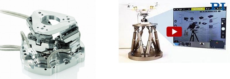
Sub-palm-sized 6-axis parallel-kinematic positioning system. (Image PI)
Drone Testing: Hexapod 6DOF Motion Platform / Motion Simulator / Stabilization / Motion Cancellation
Video - Hexapods are ideal for multi-axis motion simulation and stabilization. Applications include drone testing, simulation of hand tremors and vehicular motions for imaging subsystem design and validation. (Image: PI)
Latest hexapod designs provide very high stiffness and rigidity of their components and all moving parts, such as its joints, bearings and drive screws. These characteristics result in high natural frequencies, which make these new hexapods capable of great accuracy, and a perfect tool for photonics and optics alignment, precision machining, metrology and medical applications.
The miniature 6-axis Parallel Kinematics Hexapod Nano-Alignment System, from Physik Instrumente, is one such hexapod that is capable of delivering more than 10 lbs of force and motion in all six degrees of freedom. Resolution is as low as 50 nm with actuator encoder resolution of 5 nm and travel ranges to 40 mm linear and 60° (rotation), and a velocity of 10 mm/seconds. The high level of accuracy of the hexapod is a combination of precision assembly and testing, extremely precise parts, and sophisticated algorithms built into its vector motion controller that consider the exact tolerances of each joint and strut, and provide precise coordinates to each of the six actuators. It is possible to use this unit for alignment of optical components and lasers, Manufacturing and part placement, microscopy applications and Neuroscience that need high precision.
If minimized dimensions are of the essence, the integration of inertia-type piezo motors with the compact SpaceFab design allows for nanometer precise 6-axis motion that fits in the palm of a hand.
Vacuum Compatible Positioners
Vacuum applications are increasingly more important for many fields of Research and Industrial Manufacturing. Requirements span from vacuum levels from 10-3 mbar to 10-9 mbar. While piezo ceramic drive units can effortlessly be altered for extreme vacuum, an increasing number of motorized positioning devices are also being integrated successfully into an expanding range of vacuum applications where long travel and high precision motion is required. It is essential for positioning systems particularly developed for vacuum operation to meet a number of criteria. Only limited space is offered by vacuum chambers, and hence they need a compact design.
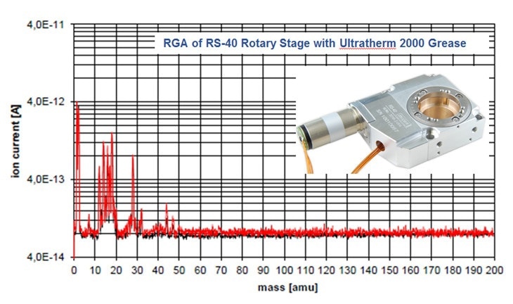
Outgassing test data of RS40 vacuum compatible rotary stage. (Image: PI miCos)
Selecting suitable components is considered to be important for the vacuum-compatibility of a positioning system. The body of the positioning device must be designed for placement in closed compartments in order to avoid outgassing leading to virtual leaks. A reduction of the surface is desired and holes and screws should be vented. Air pockets, such as in under mountings, must be avoided as they greatly delay pump-down to target pressure or even make generating a stable vacuum impossible.
UHV-compatible low-profile planar-pod 6-axis positioning systems. (Image: PI miCos)
Such a vacuum-compatible positioning device is the M-824 hexapod, a 6-Axis micropositioning and alignment system that provides high resolution motion in six degrees of freedom. It incorporates multi-axis motion to 45 mm (linear) and 25 degrees (rotation) with sub-micron resolution and repeatability, suitable for alignment and precision positioning tasks. The greatest benefit of this vacuum-compatible positioning device refers to its compact size compared to conventional six-axis positioning systems, a fact that is particularly beneficial in applications in vacuum chambers where space is at a premium. Typical applications center on multi-axis alignment of optics, semiconductor technology, X-ray monochromators and X-ray microscopy.

This information has been sourced, reviewed and adapted from materials provided by Physik Instrumente (PI) GmbH & Co KG - Worldwide.
For more information on this source, please visit Physik Instrumente (PI) GmbH & Co KG - Worldwide.