|
Ever since their discovery, carbon nanotubes have been heralded as the new wonder material of the future. Their remarkable mechanical and electronic properties destine them to play a major role in all kinds of nanotechnologies and molecular electronics [1, 2, 3]. At least two major hurdles have to be overcome in order to fulfil this potential. First, manipulation of individual tubes is at best difficult today, which prevents mass production of devices. Second, the ability to fine-tune the various properties of the material to suit particular applications has to be achieved. Thus there is a need to develop functionalization techniques for the post-growth manipulation of the properties of the nanotubes [4, 5].
For example the application of nanotubes as reinforcements in polymer composites, substrates for cell culture, sensors, actuators and field emitters with as-grown nanotubes is technologically difficult due to the nonreactive and hydrophobic nature (limited solubility in organic solvents), the relative noncleanliness of their surface (presence of an amorphous carbon layer), and the natural agglomeration of the CNTs into bundles. To overcome these problems, a modification of the carbon nanotubes by changing their surface chemical composition has proven to be efficient.
Functionalizing the carbon nanotubes with a number of functional groups is known to increase their chemical reactivity and can be used as a starting point for further chemical modification. Several methods such as chemical [6, 7, 8, 9], electrochemical [10], polymer wrapping [11], and plasma treatment have been applied to modify the CNT surface. Dai et al. describe the opening of aligned grown nanotubes capped by Fe nanorods via H2O-plasma etching, as well as acetaldehyd-plasma-activation and polymer-film deposition [12, 13]. In addition to that, other films like PMMA [14] or pyrrole [15] have been deposited. The functionalization of CNTs has been explored e.g. by using hydrogen [16], nitrogen [17], ammonia [18], O2/Ar [19], O2 [20], CF4 [21, 22], or SF6 [23] plasmas. Crucially, for use of nanotube arrays in field emission and sensor devices we have shown that plasma functionalization [24] can preserve the vertical alignment of carbon nanotube arrays.
The ends of vertically aligned carbon nanotubes or nanofibers as synthesized are normally capped by a carbon encapsulated catalyst particle. In order to enable the insertion of guest molecules (DNA, hydrogen etch) the opening of the ends of nanotubes is desired. The various methods used so far are based on three principles (i) wet chemical dissolution (ii) mechanichal break up or (ii) high temperature oxygen assisted burning. However such methods are accompanied by deleterious effects of destroying the vertical alignment and electronic structure of the nanotubes.
In this paper we report a rapid and environmental friendly low pressure glow discharge (LPGD) method to prepare carbon nanotube bucky papers with controllable wettability. We also report on the effect of room temperature LPGD on the morphology and surface chemistry of vertically aligned carbon nanofibers. Characterisation of the functionalized CNTs and nanofibers has been carried out by surface analytical techniques like SEM, ESCA, TGA, BET to find optimized parameter sets.
|
Experimental
|
Production of Carbon Nanotubes
CNT raw materials were produced at University College Cork by chemical vapour deposition (CVD) of methane over a MgO supported Co and Mo catalyst. MgO support was impregnated from an aqueous solution of Co(NO3)2.6H2O and (NH4)Mo6O24.H2O, and the solution was sonicated for 30 minutes and dried at 100 ºC overnight. The dried powder was sintered at 450 ºC for 8 hr to produce the catalyst. 0.5 g of the catalyst was placed in a quartz tube in a tube furnace. The powder was reduced by heating to 800 ºC in 10% H2/Ar at a flow rate of 200 ml min-1 for 30 min. Methane was then fed into the tube at a flow rate of 100 ml min-1. The growth period for CNTs formation was set at 800 ºC at 60 min, after which the furnace was cooled to room temperature. To purify CNTs the as-prepared catalyst/carbon mixture was treated with 3 M HNO3 and was washed by water to remove the catalyst.
Production of Aligned Grown CNTs
Aligned MWCNT were produced via Plasma Enhanced Deposition at the University of Cambridge [25]. MWCNT were grown in-situ on top of Si substrates with the aid of a thin catalyst (~5nm) layer of Ni. Using a gas flow ratio of 1:4 of Acetylene (C2H2) to Ammonia (NH3) and growth temperatures of 680°C these MWCNT were grown between 10 to 25mins to achieve the desired heights of ~0.5-1.5 μm. During the growth process a DC plasma bias of 600V is applied which maintains an electric field for aligning the MWCNT.
Plasma Treatment
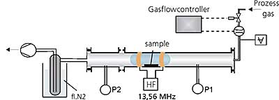
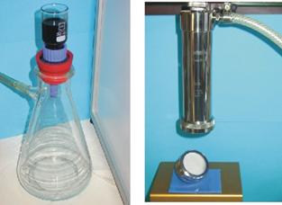
During the project, two different plasma treatment systems were built up. First, a tube reactor were used, schematically shown in Figure 1.
|
|
|
Figure 1. Schematic view of the tube reactor in horizontal design
|
The reactor is equipped with a high frequency generator (13,56 MHz), a gas inlet system with flow controllers, a vacuum pump with an upstream liquid nitrogen trap and pressure controllers. The generator enables an energy input between 10 and 600 W. The flow controller can be set to a gas flow of up to 100 sccm with one monomer gas or gas mixtures. The gas flow passes horizontally over the samples. The pumping system enables a base pressure prior to the treatment of approx 0,001mbar. The found parameter sets were then transferred to a more defined parallel plate plasma system depicted in figure 2 with a gas flow vertical to the samples.
|
|
|
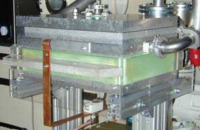
Figure 2. Parallel plate plasma treatment chamber to functionalize bucky papers and the treatment of aligned grown structures with a size of 40x30 cm2 (DIN A3).
|
This symmetrical reactor consists of two plane parallel electrodes with a size of 40×30 cm2. In the employed setup the plasma was capacitively coupled at 13,56 MHz frequency (RF) by the use of an ENI® ACG-6B plasma generator and a suitable ENI® MWH-5 impedance matching network (MKS Instruments Deutschland GmbH, Munich / Germany). The upper electrode was connected to the RF while the lower one was grounded. More details on this reactor can be found elsewhere [26].
Analytical Methods
Scanning electron microscopy (SEM; LEO 1530 VP) in combination with energy dispersive x-ray spectroscopy (EDX) was used to assess the morphological structure of the raw materials and the produced bucky papers. RAMAN-spectroscopy was carried out with the Ntegra Spectra [NT-MDT] equipped with two lasers at 632,8 nm and 488 nm emission, respectively. A grating of 1800 lines/mm yielding a resolution of 1,5 cm-1.
N2-adsorption isotherms were measured at 77 K by a gravimetric method (IGA system, Hiden Analytical, Ltd.). The adsorption measurements were carried out after preevacuation of the nanotube samples at 373 K and 1 mPa for 3h. The nanotube samples show a type II or type IV behaviour which allows the calculation of the specific surface area via the BET-method in accordance with DIN ISO 9277.
The surface analysis studies were performed by XPS/ESCA employing a Kratos Axis Ultra System equipped with a DLD-detector and a monochromatic AlKα source. Details of this set-up are described elsewhere [26, 27].
|
Results and Discussion
|
Bucky Paper Production
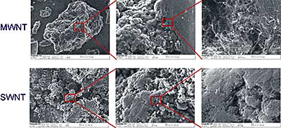
During the production process, carbon nanotubes form typically large agglomerates of entangled CNTs, often mixed with remaining little catalyst nanoparticles encapsulated in carbon nanotubes and amorphous carbon. Figure 3 represents SEM figures of MWNT and SWNT raw material produced via the CVD method. To obtain a good and stable bucky paper, those agglomerates have to be broken up, ideally to single CNTs or CNT bundles.
|
|
|
Figure 3. SEM figures of MWNT and SWNT raw material. The as-produced material consists of large, up to 100-500µm large agglomerates of entangled CNTs. The highest magnification also indicates the different shape of MWNT compared to SWNT.
|
The process parameter can also influence the specific surface area of the obtained CNT-material. From N2-adsorption measurements the following values were obtained:
Table 1. Specific surface area measured at SWNT- and MWNT-powders.
|
|
|
UCC SWNT No. 1
|
444.1 ± 2.5
|
|
UCC SWNT No. 2
|
581.3 ± 13.4
|
|
UCC MWNT No. 1
|
368.2 ± 2.6
|
|
UCC MWNT No. 2
|
555.2 ± 7.2
|
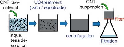
The production of carbon nanotube sheets (bucky papers) was first described by Rinzler et al. [28] as one step during the purification of SWNT raw material. A systematic optimization of the parameters influencing the bucky paper production was done along the production steps shown in the schematic view in figure 4.
|
|
|
Figure 4. Schematic view of the steps to produce bucky papers
|
Depending on the size and thickness of the finally produced bucky paper (papers up to a diameter of 150 mm can be produced) 40 mg up to 500 mg of CNT powder were dispersed in a 1% aqueous SDS (sodium dodecyl sulfate) solution using ultrasonic assistance. Also other tensides like Triton X can be used but SDS seem to be more effective. Ultrasonic assistance is indispensable to break up the agglomerates. It could be shown that an ultrasonic tip is more effective then an ultrasonic bath. With a bath up to 16 hours treatment is necessary for a good dispersion but the treatment is gentler. With an ultrasonic tip (diameter 7 mm) typical treatment times are 30min. Longer treatment times lead to a shortening of the CNTs as assessed via photon correlation spectroscopy. To remove large and undispersed particles, consecutive centrifugation for 15 min 5000 rpm is recommended. The obtained CNT-suspension is then filtered using 0,45 µm polycarbonate filter membrane. Also other membrane materials like PVDF, PTFE, PES or Nylon are suitable. But our observation is that from the PC membrane peeling off of the freshly prepared bucky paper is easier. The filtration can be done by vacuum or high pressure filtration. Figure 5 shows photographs of both filtration techniques.
|
|
|
Figure 5. Photographs of the vacuum (left) and high pressure (right) filtration technique to produce bucky papers. Depending on the equipment size, bucky papers up to 150mm in diameter can be produced.
|
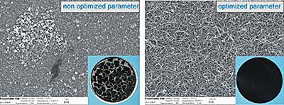
In figure 6 two SEM pictures together with the photographs of the obtained bucky papers are shown. The left part shows a picture of a BP produced with a bad parameter set. The ultrasonic treatment was to shorten the tubes, however the dispersion wasn't centrifuged thoroughly prior to the filtration. It could be clearly seen that large CNT agglomerates dominates the bucky paper leading to a brittle sheet. With optimized parameters a good entanglement of the CNTs and CNT-bundles and a stable bucky paper could be obtained.
|
|
|
Figure 6. SEM-figures and photographs of bucky papers produced under non and optimized parameters.
|
Most of the produced bucky papers were used to analyse their electromechanical properties (actuation performance) [29, 30]. For this application but also for the use of the bucky paper as substrate for cell cultivation [31], remaining SDS has to be removed. TGA-measurements, carried out at TCD, clearly indicate that the bucky paper have to be rinsed 5 times with 150 ml hot water to remove the excess SDS whereas cold water is less effective.
Plasma Treatment of Bucky Papers
To measure the actuation performance of bucky papers or to increase the ability of cells to settle and proliferate at it, a hydrophilization of the paper surface is required. As produced bucky papers typically have non-wetting properties with contact angles of 90° up to 130°. This can be traced back to the hydrophobic nature of the CNTs. To measure the electromechanical properties, an electrolyte is required [32]. A hydrophilization of the bucky papers due to a plasma treatment should lead to an instant wetting and better penetration of the electrolyte into the CNT mesh.
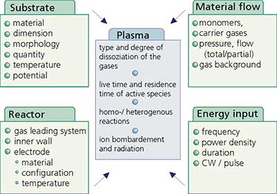
To optimize the plasma process several parameters have to be considered due to their influence on the kind and amount of active species in the plasma zone. Figure 7 summarizes the most important ones.
|
|
|
Figure 7. Parameters influencing the plasma treatment
|
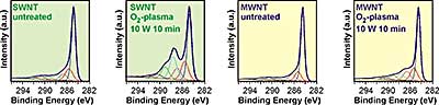
We have investigated the influence of the monomer gas, the power, the gas flux, and the treatment time. The assessment of the plasma functionalization was mainly done by X-ray photoelectron spectroscopy (XPS/ESCA). In figure 8 typical C1s spectra of SWNT, MWNT and plasma treated MWNT are shown. The SWNT bucky paper in this case was made from an arc discharge raw material. The additional peak at approximately 287 eV, attributed to the enhancement of oxygen functionalities is more pronounced for the SWNT material.
|
|
|
Figure 8. C1s spectras of SWNT, MWNT and an Ar/O2-plasma treated bucky paper.
|
In the literature different approaches have been discussed concerning the deconvolution of the C1s peak of carbon nanotubes. Some use a graphite peak shape for the large peak at 284,6 eV with the tail at the high energy binding site[33, 34, 35], others distinguish between sp2- and sp3-carbon at 284,6 eV (C1) and at 285,1 eV (C2), respectively[36, 37]. The peaks with binding energies higher than 290 eV have been interpreted as π-π* transitions (shake ups)[38], as O=C-O-C=O / carbonate [39] or have been neglected [40]. The three main peaks centered at 286,7 eV (C3), 287,9 eV (C4), and 289,2 eV (C5) that emerge after plasma oxidation are generally attributed to C-O (alcohol/ether), C=O (keton/aldehyd), and O-C=O (carboxyl/ester) groups, respectively. All components were fitted by using a Gaussian/Lorentzian (70/30) line shape after a linear background substraction and constant peak positions and FWHMs.
To investigate the role of hexagonal layers on the plasma induced modification we have compared MWNT and SWNT material treated with nitrogen, N2/O2 (50:50), and oxygen plasma, respectively. The plasma power was set to 10 W and the applied treatment times were 10 sec or 10 min, respectively. The obtained elemental compositions are given in table 2.
Table 2. Comparison of the elemental composition of SWNT and MWNT material after different plasma treatments with increased oxidation potential and 2 different treatment times.
As expected, longer treatment times and higher oxidation potential of the plasma lead to higher oxygen content. Taking a closer look at the oxygen content it can furthermore be concluded that in all cases the degree of oxygen functionalization is higher for the SWNT material than for the MWNT material. This can be explained by the information depth of XPS. The functionalization of the MWNT-material occurs only at the outermost 1-3 CNT-layers. The information depth of XPS (approx. 5-10nm) includes the unmodified inner shells too, resulting in a reduced O/C-ratio for the MWNTs.
The oxygen functionalities were substantially improved after plasma treatment in N2 (for SWNTS increased from 5.1 to 15.7 at%; for MWNTs increased from 2.5 to 13.2 at%), whereas the incorporation of nitrogen was moderate ( 0.5 to 2.5 at%). This significant uptake of oxygen can be explained by considering the large number of defects generated during the plasma treatment. The introduction of defects in the hexagonal lattice leaves the surface with very highly reactive sites capable of adsorbing oxygen.
High plasma power and treatment times were efficient not only to introduce oxygen functionalities on the first few surface layers of the CNTs, but also to remove amorphous carbon and even destroy the nanotubes up to a full burning (see also next section). This is in agreement with the decrease in specific surface area measured at MWNTs bucky paper before and after treatment in Ar/O2 plasma. Whereas the raw material has a specific surface area of 368 ± 3 m2/g the pristine and plasma treated bucky paper shows values of 203 ± 2 m2/g and 188 ± 2 m2/g respectively. Therefore plasma treatment under optimized conditions can serve as a purification process able to etch non crystalline carbon related impurities.
A gentler but also effective hydrophilization can be achieved by using nitrogen plasma followed by a deliberate post-treatment oxidation with oxygen. Here, the nanotubes are activated by the nitrogen plasma leading to a significant amount of radicals, as assessed by electron spin resonance (ESR). The consecutive flooding of the plasma reactor with oxygen enables the reaction of the biradical oxygen with the radicals formed at the nanotube surface. The bucky papers treated with this method show also an instant wetting and contact angles below 10°.
Plasma Treatment of Aligned Grown CNTs
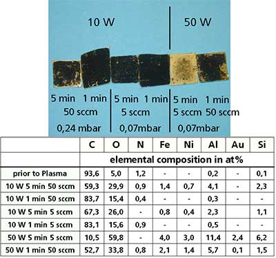
Initially plasma treatments were carried out on entangled CNTs deposited by drop dry technique on gold coated silicon wafers. The left hand side of figure 9 shows optical micrographs of the entangled samples after oxygen plasma treatment at various conditions The table at the right side summarizes the elemental composition obtained by electron spectroscopy chemical analysis (ESCA). All the experiments were carried out in the horizontal tube reactor. It is clear, that within this reactor a strong oxidation occurs by using oxygen as process gas and a power of 50 W. After 5 minutes treatment at 50 W the CNT coating was burned off.
|
|
|
Figure 9. Optical micrographs of entangled CNTs deposited on Ag/Si by drop dry technique after different oxygen plasma treatments, together with their elemental compositions.
|
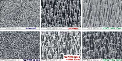
Subsequently, the plasma treatment of vertically aligned CNTs grown on a Si substrate was carried out with the aim of opening their end. Due to the top growth mechanism the nickel catalyst is located at the tip of the CNTs seen as white dots in the SEM-pictures The experiments were performed in the parallel-plate reactor. Due to the larger plasma zone, the effective power per cm2 is smaller compared to that of the tube reactor. Different monomer gases were assessed including oxygen, nitrogen, hydrogen, water as well as argon/oxygen- and hydrogen/oxygen-mixtures. The roles of power (10 W, 50 W), gas flux, pressure and treatment time (between 10 sec and 10 min) were also investigated. We found that the harsh treatments necessary for opening the CNTs were severely disrupting the shape and vertical alignment of the CNTs. Figure 10 presents typical SEM images.
|
|
|
Figure 10. SEM-pictures of aligned CNTs before and after plasma treatment. After short treatment times (10sec) at 10 W power no disruption is visible whereas longer treatment times or higher power destroy the shape of the tubes without opening of the end caps.
|
We found that oxygen plasma treatment leads to a significant disruption of the vertical alignment configuration even after short treatment times of 60 sec. Ar/O2- and H2/O2-mixtures can be applied up to approx 60 sec without strong alteration of the tube shape whereas longer times show the same deleterious effects. Plasma treatments employing reduced oxidation potentials like those produced by molecular nitrogen resulted on an unaltered vertical CNT configuration even after 10 min.
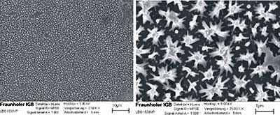
Acid solutions such as hydrochloric acid have been shown to assist the opening of plasma treated SWNTs [41]. The plasma treatment leads to a destruction of nanotube wall, enabling the HCl to react with the iron catalyst particles and burn away the tube caps. In our study, employing plasma treated MWNTs (150 nm in diameter) a consecutive wet chemical treatment after mild plasma conditions lead to a "tipi-building" of the CNTs due to capillary forces without opening the ends. The 3D network structure is illustrated on the SEM-pictures of figure 11. We envisage that more harsh conditions (longer treatment times) are needed to expose the catalyst particles; such studies are underway.
|
|
|
Figure 11. "Tipi-building" of aligned grown CNTs after a wet chemical treatment.
|
|
Conclusions
|
|
Bucky papers were successfully produced after optimization of the production steps. SDS was identified as appropriate Tenside together with an ultrasonic tip treatment to obtain good CNT suspensions. The ultrasonic treatment was set to 30 min to avoid significant shortening of the CNTs. Remaining CNT agglomerates were removed by centrifugation prior to the filtration over a 0,45 µm pore size polycarbonate membrane. PC-membranes were assessed as best to peel of the bucky papers. The effects of plasma treatment on the surface wettability of carbon nanotube bucky papers and aligned nanotubes have been systematically investigated A hydrophilization of the produced bucky papers was successfully demonstrated by plasma treatment using oxygen containing process gases or post treatment reaction with oxygen after plasma activation. As a result, an instant wetting and contact angles <10° was obtained. We also found that under gentle oxidation parameters the vertical alignment of MWNTs remains unchanged whereas stronger conditions destroy the CNT shape without opening the end caps.
|
Acknowledgment
|
|
The authors acknowledge the European Union for funding this project within the EU Specific Targeted Research Project DESYGN-IT (No NMP4-CT-2004-505626)
|
References
|
|
1. M. S. Dresselhaus, G. Dresselhaus, P. Avouris, Carbon Nanotubes: Synthesis Structure, Properties, and Applications; Springer, Berlin, 2001.
2. R. H. Baughman, A. A. Zakhidov, W. A. de Heer, Science 297 (2002) 787.
3. P. Avouris and J. Chen, Materials Today 9 (2006) 46.
4. A. Hirsch, O. Vostrowsky, Functionalization of carbon nanotubes, Springer Berlin / Heidelberg, 2005.
5. C.A. Dyke, J.M. Tour. Chem. Eur. J. 10 (2004) 81.
6. H. Murphy, P. Papakonstantinou, T.I.T. Okpalugo, J. Vac. Sci. Technol. B 24 (2006) 715.
7. F.H. Gojnv, J. Nastalczyk, Z. Roslaniec, K. Schulte, Chem. Phys. Lett, 370(5-6) (2003) 820.
8. U. Dettlaff-Weglikowska, J. M. Benoit, P. W. Chiu, R. Graupner, S. Lebedkin, and S. Roth, Curr. Appl. Phys. 2 (2002) 497.
9. T.I.T. Okpalugo, P. Papakonstantinou, H. Murphy, J. McLaughlin, and N. M. D. Brown, Carbon 43 (2005) 2951.
10. J. L. Bahr, J. P. Yang, D. V. Kosynkin, M. J. Bronikowski, R. E. Smalley, and J. M. Tour, J. Am. Chem. Soc. 123 (2001) 6536.
11. M. J. O’Connell et al. Chem. Phys. Lett. 342 (2001) 265.
12. L. Dai, Radiation Physics and Chemistry, 62 (2001) 55.
13. Q. Chen, L. Dai, M. Gao, S. Huang, A. Mau, J. Phys. Chem. B, 105 (2001) 618.
14. R. E. Gorga, K. K. S. Lau, K. K. Gleason, R. E. Cohen, Journal of Applied Polymer Science, 102 (2006) 1413.
15. D. Shi, J. Lian, P. He, L. M. Wang, W. J. van Ooij, M. Schulz, Y. Liu, D. B. Mast, Applied Physics Letters 81, (2002) 5216.
16. B. N. Khare, M. Meyyappan, A. M. Cassell, C. V. Nguyen, J. Han, Nano Lett. 2 (2002) 73.
17. B. N. Khare, P. Wilhite, B. Tran, E. Teixeira, K. Fresquez, D. N. Mvondo, C. Bauschlicher, M. Meyyappan, J. Phys. Chem. B, 109 (2005) 23466.
18. B. N. Khare, P. Wilhite, R. C. Quinn, B. Chen, R. H. Schingler, B. Tran, H. Imanaka, C. R. So, C. W. Bauschlicher, M. Meyyappan, J. Phys. Chem. B, 108 (2004) 8166.
19. H. Bubert, S. Haiber, W. Brandl, G. Marginean, M. Heintze, V. Brüser, Diamond and Related Materials, 12 (2003) 811.
20. T. Xu, J. Yang, J. Liu, Q. Fu, Applied Surface Science, 253 (2007) 8945.
21. L. Valentini, D. Puglia, I. Armentano, J.M. Kenny, Chemical Physics Letters 403 (2005) 385.
22. N. O. V. Plank, L. Jiang, R. Cheung, Applied Physics Letters, 83 (2003) 2426.
23. N. O. V. Plank, R. Cheung, Microelectronic Engineering, 73-74 (2004) 578.
24. G. Abbas, P. Papakonstantinou, G.R.S. Iyer, IW. Kirkman, LC. Chen, Phys. Rev B, 75 , 1954429 (2007).
25. M. Chhowalla, K.B.K. Teo, C. Ducati, N.L. Rupesinghe, G.A.J. Amaratunga, A.C. Ferrari, D. Roy, J. Robertson and W.I. Milne, Journal of Applied Physics 90 (2001) 5308.
26. U. Vohrer, D. Hegemann, C. Oehr, Anal. Bioanal. Chem., 375 (2003) 929.
27. U. Vohrer, C. Blomfield, S. Page, A. Roberts, Applied Surface Science, 252 (2005) 61.
28. A. G. Rinzler, J. Liu, H. Dai, P. Nikolaev, C. B. Huffman, F. J. Rodriguez-Macias, P. J. Boul, A. H. Lu, D. Heymann, D. T. Colbert, R. S. Lee, J. E. Fischer, A. M. Rao, P. C. Eklund, R. E. Smalley, Applied Physics A (1998) 29.
29. U. Kosidlo, D. G. Weis, K. Hying, M. H. Haque, I.Kolaric, Azojono 2007 to be published
30. U. Vohrer, I. Kolaric, M. H. Haque, S. Roth and U. Detlaff-Weglikowska, Carbon 42 (2004) 1159.
31. U. Vohrer, Fraunhofer IGB, Biennal Report 2004/2005, 48-49 (2005) http://www.igb.fraunhofer.de/WWW/GF/GrenzflMem/nano/CNT/en/CNT_references.en.html
32. Baughman, R. H.; Cui, C.; Zakhidov, A. A.; Iqbal, Z.; Barisci, J. N.; Spinks, G. M.; Wallace, G. C.; Mazzoldi, A.; de Rossi, D.; Rinzler, A. G.; Jaschinski, O.; Roth, S.; Kertesz, M., Nanotube Actuators. Science 284 (1999) 1340.
33. H. Bubert, S. Haiber, W. Brandl, G. Marginean, M. Heintze, V. Brüser, Diamond and Related Materials 12 (2003) 811.
34. S. Haiber, A. Xingtao, H. Bubert, M. Heintze, V. Brüser, W. Brandl, G. Marginean, Anal Bioanal Chem., 375 (2003) 875.
35. A. Felten, C. Bittencourt, J. J. Pireaux, G. Van Lier, J. C. Charlier, Journal of Applied Physics, 98 (2005) 074308.
36. C. Pirlot, I. Willems, A. Fonseca, J. B. Nagy, J. Delhalle, Advanced Engineering Materials, 4 (2002) 109.
37. H. Ago, T. Kugler, F. Cacialli, W. R. Salaneck, M. S. P. Shaffer, A. H. Windle, R. H. Friend, J. Phys. Chem. B 103 (1999) 8116.
38. Y. Q. Wang, P. M. A. Sherwood, Chem. Mater., 16 (2004) 5427.
39. Parekh, B. D., T.; Knight, P.; Santhanam, K.S.V.; Takacs, G.A J. Adhesion Sci. Technol., 20(16) (2006) 1833.
40. W. H. Lee, S. J. Kim, W. J. Lee, J. G. Lee, R. C. Haddon, P. J. Reucroft, Applied Surface Science 181 (2001) 121
41. Huang, S.; Dai, L. J. Phys. Chem. B 2002, 106, 3543-3545.
|
|
|
|