The NanoPatterning and Visualization Engine (NPVE) expands the capabilities of your dual-column system to new heights. As an add-on to your Carl Zeiss system, the NPVE enables rapid prototyping of features from nanometers to millimeters, extensive control over patterning parameters and extreme field of view imaging up to 1 GigaPixel per image, all in an integrated, intuitive user interface.
The NPVE brings together dual 16 bit scan generator technology and supersampling signal acquisition hardware with a floating point, vector scan engine. Operated through an intuitive user interface, the NPVE smoothly integrates simultaneous control of both the FIB-SEM (CrossBeam®) and SEM, real-time imaging during patterning and automated control of the microscope through SmartSEM. Simple to learn yet extremely powerful, the NPVE system is the solution of choice for a wide range of NanoPatterning and Imaging applications. Its ease of use allows even novice users to begin solving complex problems in nanoprototyping, with or without gas chemistry, quickly and easily.
The NPVE combines extensive, flexible NanoPatterning capability with increasingly vital Visualization of signals generated by the patterning beam, bringing together a wealth of information which complements the existing imaging capabilities of the CrossBeam® instruments.
In addition to the NanoPatterning features of the NPVE, the user may acquire images up to one billion pixels in size (32k x 32k), enabling high resolution, extremely large field of view imaging. Additional options allow automated acquisition and stitching of large area Mosaics creating a montage of many contiguous high resolution images.
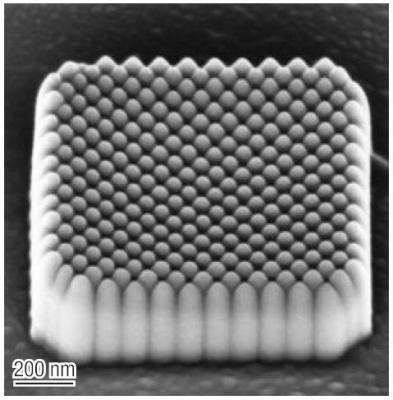
A 1 µm X 1 µm square of Electron Beam deposited silicon oxide pillars. The patterning angle within the square shape was set to 45°, with spacing chosen to have the pillars just contacting.
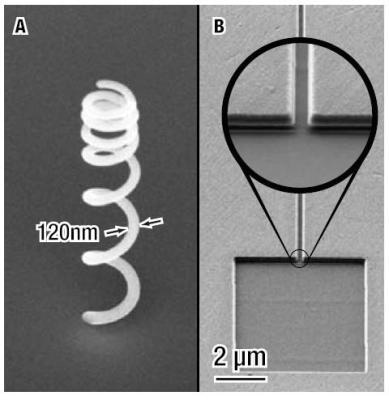
A: 600 nm diameter FIB-deposited 3D coil. B: Reservoir and a nano-channel 20 µm long and 200 nm in width. Real-time visualization while milling allows a smooth, flat-bottomed transition from channel to reservoir.
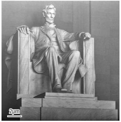
A FIB grayscale rendering of the Lincoln Memorial, patterned into silicon. An unmodified photograph was used as the data source. The total patterning time was approximately ten minutes.
NPVE Features and Applications
Array Builder
Creating arrays of repetitive structures is straightforward using the NPVE Array Builder. Different array styles can be constructed including regular and radial arrays. The Array Builder has proven to be indispensable for gas process optimization as a wide range of parameters can be systematically varied on a shape-by-shape basis for rapid design of experiments.
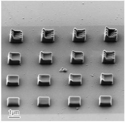
A 4 by 4 array of rectangles used for electron beam assisted deposition. The dwell point spacing was varied by row and by column.
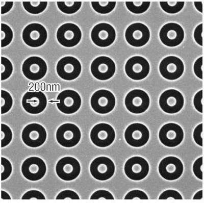
A portion of an array of annular shapes, each 450 nm in diameter, with a 1 µm spacing (pitch) between shapes.
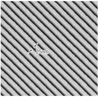
Isometric view of grating of 25 nm lines spaced by 100 nm, directly patterned using a 10 pA ion beam.
Operation Recipes
Determining optimal patterning parameters to achieve the very best results may require significant effort on the part of a novice user.
To facilitate this process, the NPVE ships with a number of Operation Recipes which encapsulates the optimal patterning parameters across a range of beam currents, for many common tasks such as precision milling or gas-based chemistries.
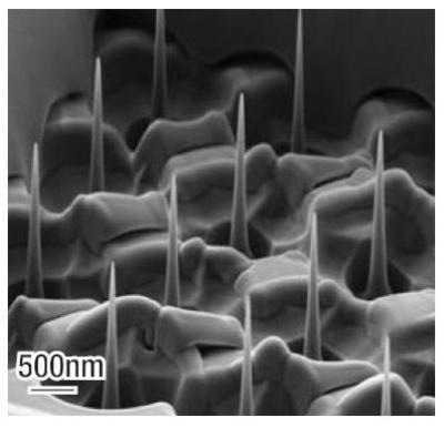
Nano-Pillar arrays
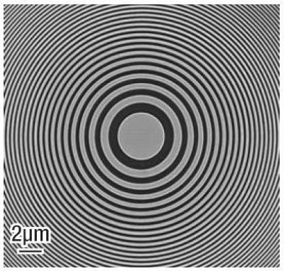
Zone plate
Nano-scale channel structures
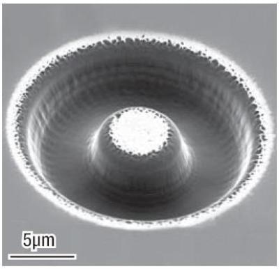
Half-torus milled into diamond
Users simply choose an appropriate recipe, which automatically applies these parameters to any shape with “one click”. Users may also modify or generate their own recipes using the Operation Recipe Editor.
Additional Features
In addition to the features shown, the NPVE has numerous additional capabilities. Please contact your sales representative to discuss your particular application, and how the NPVE can assist in making your application a success.
NPVE Features
Basic Shapes
The NPVE has nine basic shapes which can be used or combined to create more complex shapes. Each shape is composed of fully-editable nodes and segments in a manner familiar to anyone who has used graphics software.
The NPVE also comes with a file importer which can read and convert 2D drawings in several industry standard formats.
Basic Shape List:
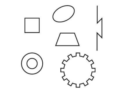
- Rectangle
- Ellipse
- Ring
- Line
- Polyline
- Polygon
- Trapezoid
- Text
- Spot
Patterning Parameters
Choosing the optimal patterning parameters greatly affects the outcome of an experiment. For this reason the NPVE interface offers a high degree of flexibility in optimizing how the beam is moved across the sample. Virtually all parameters relating to beam positioning can be set - or the user can choose a previously defined Operation Recipe which will then automatically set the Patterning Parameters for the chosen shapes.
Void Shapes
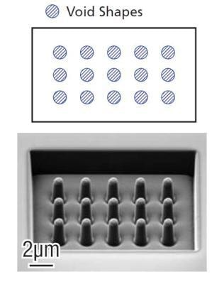
Using “Void” shapes, the NPVE offers a convenient method to prevent critical sample regions from being patterned by the beam. Any filled shape may be turned into a Void. In turn, any shape which contacts a Void will then have the region which contains all or a portion of the Void excluded from patterning.
Parallel Patterning
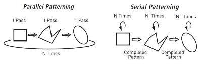
Patterning multiple shapes in parallel, rather than serially completing one shape and moving onto the next has distinct advantages, particularly when using gas chemistries or milling high aspect ratio structures. The NPVE supports parallel or serial patterning of all shapes or selected subsets of shapes.
Vector Scanned Shapes
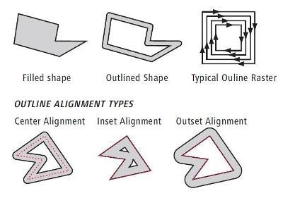
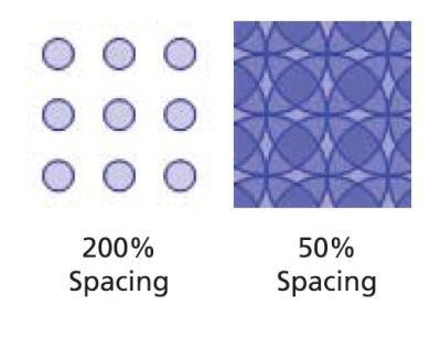
Traditionally, shapes are filled with a raster-like scan algorithm. The NPVE supports this traditional style (indeed allowing an arbitrary scan direction to be specified), but it also supports vector scanning of the shape outline. Outline scanning can be used to completely fill a shape, or to trace the perimeter of the shape in a manner that smoothly follows the shape's outline. Outline scans can be set for Center, Inset or Outset Alignment, either with a specified thickness, or to the point of filling the shape. As elsewhere, the NPVE allows complete control of patterning parameters such as the dwell point spacing along each "path" and between "paths", how corners are mitered, etc.
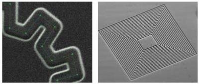
Dwell point simulation at 50% overlap, of an outline shape with ten-fold symmetry
Set Operations
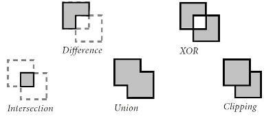
Creating complex shapes is made easier by using the NPVE Set Operations. Individual shapes may be combined with Set Operations to create the Union, Difference, Intersection, XOR or Clipped version of the shapes. Each derived shape remains fully editable, with new nodes being determined by the particular Set Operation employed. Using Set Operations, overlapping shapes and the resulting erroneous double dosing error can be eliminated.
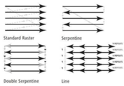
Patterning Styles
The particular scan strategy employed has a significant impact on the results achieved. NPVE Patterning Styles allow the user to specify a range of scan strategies.
Offset Fill
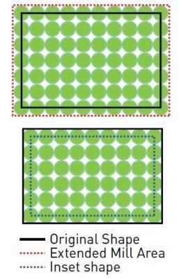
Spot size, redeposition of material, gas deposition or etch rates, etc. all contribute to making the final shape slightly larger or smaller than the as-drawn shape. Each shape has an Offset parameter which, once calibrated for a particular Operation, allows the NPVE to automatically contract or expand the shape by the amount required to meet the exact dimensional tolerances.
Live View Patterning
Visualization of the patterning process from the perspective of the patterning beam, not merely viewing with the SEM while milling with the FIB, has proven to be critical to the success in many applications of FIB NanoPatterning.
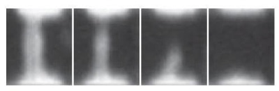
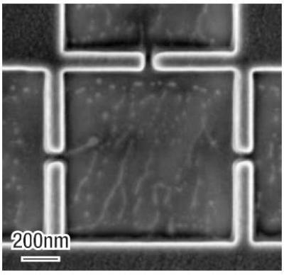
Live View Patterning of the cutting of a nano-wire at the bottom of a deep hole.
The NPVE displays real-time "zoom view" images of shapes as they are patterned, allowing precise alignment, drift correction and observation of the patterning process.
FIB Text
For convenient tracking of data, all experiments can be readily marked in-situ using the FIB Text option. All MS Windows™ fonts are available and the text can be patterned in the same manner as any other shape, including applying Operation Recipes to enable gas chemistries.
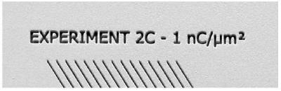
FIB Text annotating experimental conditions
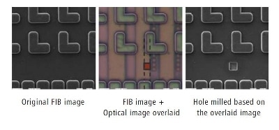
Image Overlay
In certain applications the precise positioning of shapes can be made much simpler by overlaying a previously acquired image, or an image from another source such as an optical microscope. The NPVE supports image overlay, alignment and transparency adjustment.
This information has been sourced, reviewed and adapted from materials provided by Carl Zeiss.
For more information on this source, please visit Carl Zeiss.