In digital circuits, insulating dielectrics separate the conducting parts (wire interconnects and transistors) from one another. As components have scaled down and transistors have gotten closer and closer together, the insulating dielectrics have thinned to the point where charge build-up and crosstalk adversely affect the performance of the device. It is this reduction in scale that drives the need for insulating materials with lower dielectric constant.
A Low-κ material is one with a small value for dielectric constant relative to silicon dioxide (SiO2), a former dielectric of choice. The dielectric constant of SiO2 is 3.9. This number is the ratio of the permittivity of SiO2 divided by the permittivity of vacuum, εSiO2/ε0, where ε0 = 8.854x10⁻⁶ pF/μm. There are many materials with lower dielectric constants, but few of them can be suitably integrated into a semiconductor manufacturing process [1].
At the extreme, dry air (20°C, 1 atm) has a dielectric constant of 1.00059 [2], but dry air cannot keep conducting materials mechanically separated, so it cannot be used as an insulator. However, as one incorporates material for structure, the dielectric constant also increases. Therefore, the optimization problem in materials development for semiconductors is to lower the permittivity of the dielectric material as far as possible without compromising mechanical integrity, as quantified by the Young's modulus. Generally, processes purposed for reducing permittivity (such as pore introduction) also have the effect of reducing Young's modulus.
Instrumented indentation is commonly employed in the semiconductor industry to measure the Young's modulus of Low-κ films deposited on silicon wafers. Two typical wafers are shown in Figure 1. Commonly, these films are less than 200nm thick.
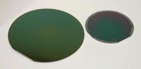
Figure 1. Whole silicon wafers, coated with Low-κ materials.
Without any correction for influence of the underlying silicon substrate, one faces a compromise between uncertainty and error. At very small displacements, the error due to the substrate influence is small, but the uncertainty is greater due to surface roughness, tip variations, vibration, temperature variations, etc. As indentation depth increases, the uncertainty decreases, but the error due to substrate influence increases. The issue is even more complex because many Low-κ films present a "skin" with properties that are not representative of the bulk of the film. When testing such a film by instrumented indentation, the near-surface data are affected by this skin, and data at larger depths are affected by the substrate, leaving no domain in which the properties of the film alone can be obtained.
Thus, the purpose of this work was to apply an analytic model to the analysis of Low-κ films tested by instrumented indentation in order to obtain the Young's modulus of the film alone. Such a model was recently introduced and verified by finite-element analysis [3]. Developed by KLA, it is referred to as the "Hay-Crawford" model.
The Hay-Crawford Model
The Hay-Crawford model provides an analytic means of accounting for substrate influence on measured modulus. The model presumes that apparent modulus has already been determined. Here, "apparent modulus" means modulus calculated according to the method of Oliver and Pharr [4]. This method has been explained in detail elsewhere [5, 6].
The Hay-Crawford model is expressed in terms of shear modulus; the general relation between Young's modulus (E), shear modulus (μ), and Poisson's ratio (υ) is E = 2μ(1+ υ). The Hay-Crawford model presumes that the film acts in series and in parallel with the substrate as illustrated in Figure 2.
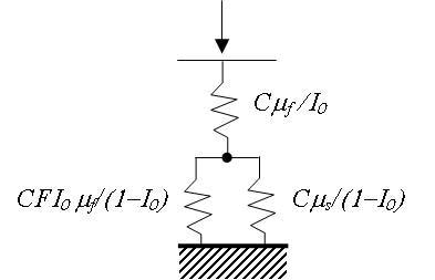
Figure 2. Schematic of the proposed model. Top spring represents the action of the film. Bottom two springs represent the film and substrate acting in parallel.
Thus, the apparent (substrate-affected) shear modulus (μa) is related to the shear modulus of the film (μf) and that of the substrate (μs) through this expression:
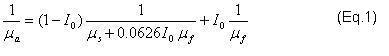
The weighting function, I0, is due to Gao [7]; it provides for a smooth transition between the influence of the film and that of the substrate. The expression for I0 is provided in Figure 3 where it is plotted against normalized contact radius (a/t).
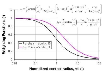
Figure 3. Weighting functions for shear modulus (I0) and Poisson's ratio (I1).
Thus, the shear modulus of the film is calculated from the apparent value by solving Eq. 1 for μf :
where A = 0.0626I0 /μa, B = μs /μa + I0 – 1 – 0.0626I02, and C = - I0 /μs.
Finally, the Young's modulus of the film is calculated from the shear modulus and Poisson's ratio as
Ef = 2μf (1+υf). (Eq. 3)
Calculation of μa from standard indentation results for use in Eq. 1 requires a value for Poisson's ratio. The weighting function I0 also utilizes Poisson's ratio. But which value should be used — that of the film or that of the substrate? To be sure, this problem is of the second order, but Gao also suggests a weighting function, I1, for handling the transition in Poisson's ratio, so that the apparent Poisson's ratio, υa, is calculated as
Eq. 4 provides the value for Poisson's ratio used in the calculation of μa and I0. It should be noted that if the film and the substrate have the same Poisson's ratio (that is, if υs = υf = υ), then Eq. 4 reduces to υa = υ. The expression for I1 is also provided in Figure 3, where it is plotted against normalized contact radius.
Experimental Method
Two Low-κ films on silicon were tested; the thickness of the first film was 1007 nm and the thickness of the second was 445 nm. Figure 4 shows the two samples mounted for testing. Results have been reported for these same samples before, but without any accounting for substrate influence [8]. In this work, we compare results obtained by the Hay-Crawford model to those previously reported.
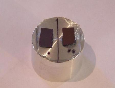
Figure 4. Two Low-κ samples, as mounted for testing in the KLA Nano Indenter G200.
The two Low-κ samples were tested in a KLA lab with a KLA Nano Indenter G200 utilizing the Continuous Stiffness Measurement option and a DCM II head fitted with a Berkovich indenter. Results were achieved using the KLA NanoSuite test method "G-Series DCM Continuous Stiffness Measurement for Thin Films". This test method implements the Hay-Crawford model to achieve substrate-independent measurements of Young's modulus.
It should be noted that this method does not correct measurements of hardness for substrate influence. However, hardness measurements are generally less sensitive to substrate influence because the extent of the plastic field is much smaller than the extent of the elastic field. Even when there is a substantial difference between film hardness and substrate hardness, the hardness measured at 10% of the film thickness usually manifests negligible substrate influence.
KLA Nano Indenters have been the industry choice for thin-film testing precisely because of the Continuous Stiffness Measurement option, which measures elastic contact stiffness (S) dynamically. With the Continuous Stiffness Measurement option, every indentation test returns complete depth profiles of Young's modulus and hardness. Using this option, eight tests were performed on each Low-κ sample. Loading was controlled such that the loading rate divided by the load (P'/P) remained constant at 0.05/sec; loading was terminated at a penetration depth of 200 nm or greater. The excitation frequency was 75 Hz and the excitation amplitude was controlled such that the displacement amplitude remained constant at 1 nm.
Results and Discussion
Results are summarized in Table 1. Figures 5 and 6 show the Young's modulus as a function of penetration depth for each sample.
i
| 1 |
2
|
3
|
4
|
5
|
6
|
7
|
8
|
9
|
| |
|
|
Results, Standard
|
Results, by Eqs. 1-3
|
| Sample |
N
|
Thickness nm
|
Range* nm
|
Ea GPa
|
σ(Ea) GPa
|
Range** nm
|
Ef GPa
|
σ(Ef) GPa
|
| low-κ 1 |
8
|
1007
|
35-40
|
4.69
|
0.07
|
95.9-105.4
|
4.34
|
0.06
|
| low-κ 2 |
8
|
445
|
25-30
|
8.23
|
0.13
|
42.2-46.8
|
7.46
|
0.12
|
* Selected by eye
** Corresponds to 9.5%-10.5% of film thickness
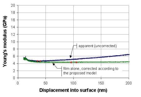
Figure 5. Low-κ 1 on silicon substrate, tf = 1007 nm.
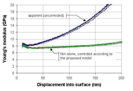
Figure 6. Low-κ 2 on silicon substrate, tf = 445 nm.
The blue traces are the uncorrected values; they show what would be achieved without any correction for substrate influence using a standard NanoSuite test method such as "G-Series DCM Continuous Stiffness Measurement Standard Hardness, Modulus, and Tip Cal". These blue traces show Young's modulus increasing as a function of displacement because the silicon substrate, which is much stiffer, increasingly affects the measurement. The effect is more pronounced for thinner film; the blue traces increase most rapidly for the "Low-κ 2" sample because it is the thinnest film tested in this work.
The red diamonds show the range used to calculate the (uncorrected) Young's moduli in the fifth column of Table 1. Logistically, these diamonds are placed by the user so as to select data that are, in the user's judgment, free from both surface anomalies and substrate influence.
The green traces of Figures 5 and 6 are the values calculated according to Eqs. 1–3. The red diamonds show the range used to calculate the Young's moduli in the eighth column of Table 1, but diamonds were placed automatically by the software at 9.5% and 10.5% of the film thickness, respectively, so as to reduce the amount of user judgment involved in deriving results. The corrected Young's moduli cited at 10% of the film thickness (Table 1, column 8) are significantly lower than what was previously reported for these samples (Table 1, column 5).
Another important observation is that when a correction for substrate influence is employed, the results can be taken from deeper into the film, where surface anomalies have less influence. As a result, the standard deviations are smaller, as can be seen by comparing values in the sixth and ninth columns of Table 1.
Conclusions
The KLA Nano Indenter G200 with a DCM II head is the industry choice for these measurements because of its high precision, speed, ease of use, and the Continuous Stiffness Measurement option, which delivers properties as a continuous function of penetration depth. In this work, KLA NanoSuite Explorer software was used to implement an analytic model that accounts for substrate influence. Test methods with this analysis are now available to customers with KLA NanoSuite Professional software.
Having a model that accounts for substrate influence on Young's modulus affords several practical advantages:
- Reported moduli are for the film alone
- Less user influence because depth range for calculating moduli does not have to be selected "by eye"
- Less uncertainty because results are obtained at deeper penetration depths
References
- https://en.wikipedia.org/wiki/Low-%CE%BA_dielectric
- http://hyperphysics.phy-astr.gsu.edu/Hbase/tables/diel.html
- J.L. Hay, "A new model for measuring substrate-independent Young's modulus of thin films by instrumented indentation," KLA application note (2010).
- W.C. Oliver and G.M. Pharr, "An improved technique for determining hardness and elastic modulus using load and displacement sensing indentation experiments," J. Mater. Res., 7(6):1564–1583 (1992).
- J.L. Hay, "Introduction to instrumented indentation testing," Experimental Techniques 33(6):66–72 (2009).
- J.L. Hay, P. Agee, and E.G. Herbert, "Continuous stiffness measurement during instrumented indentation testing," Experimental Techniques 34(3):86–94 (2010).
- H. Gao, C.-H. Chiu, and J. Lee, "Elastic contact versus indentation modeling of multi-layered materials," Int. J. Solids Structures, 29:2471–2492 (1992).
- J.L. Hay, "Young's modulus of dielectric Low-κ materials," KLA application note (2010).

This information has been sourced, reviewed and adapted from materials provided by Nanomechanics, Inc., a KLA-Tencor company.
For more information on this source, please visit KLA.
Disclaimer: The views expressed here are those of the author expressed in their private capacity and do not necessarily represent the views of AZoM.com Limited T/A AZoNetwork the owner and operator of this website. This disclaimer forms part of the Terms and conditions of use of this website.