Introduction
The term bicomponent fiber, also known as a conjugate fiber, refers to a single fiber that includes two varied polymer components inside the same filament. The production of bicomponent fibers is not a new concept - Dupont already introduced this idea in the mid 1960s. However, the processes used to produce bicomponent fibers were not streamlined, which recently led to the development of new material systems and their manufacturing technologies.
The increased interest in bicomponent fibers is due to the fact that characteristics of two entirely different polymer components can be used in one fiber. The option of two components can be varied and can lead to many types of cross-sectional geometry, like sheath-core, side by side, islands-in- the-sea, etc.
The manufacturing process and their related applications mostly control these different cross-sections. This article focuses on single bicomponent fibers with a sheath-core cross-sectional geometry, where a single polymer component (core) is fully encapsulated by another polymer (sheath).
When diverse functionalities are required in the sheath, the sheath-core geometry is beneficial, and the core may be responsible for reduced cost, strength, etc. Excellent adhesion may exist between the sheath and the fiber core, but when there is no adhesion, a contoured interface between the core and sheath can introduce mechanical interlocking between the two phases.
The sheath-core bicomponent fibers are utilized in a wide range of applications. To better illustrate this point, bicomponent fibers with highly elastic behavior offer mechanical interlocking in nonwovens and can crimp very easily. They can even provide strength in nonwovens if the sheath component is subjected to heat treatment.
The presence of two varied materials in the fiber has made it easy to create fibers with better water adsorption or thermal insulation, without affecting their mechanical integrity. A better insight into the polymer fibers’ mechanical behavior is imperative for nonwoven and woven textile industries. In the development of new fiber materials, dynamic mechanical analysis has continued to be an essential component.
In recent years, a new experimental technique called continuous dynamic analysis (CDA) has revealed that the dynamic mechanical properties of a polymer fiber considerably changes with their deformation. The measurement of this difference in the material’s dynamic modulus is a critical factor to gain a better understanding of the entire deformation mechanism of polymeric materials. In this article, CDA is used to interpret the tensile deformation behavior of bicomponent polymer fibers.
Theory
Prior to discussing the outcomes on bicomponent fibers, the study introduces the concept behind the continuous dynamic mechanical analysis and tensile measurements. In a tensile experiment, the engineering stress is defined as:
 |
Equation 1 |
where, F represents the applied force and A0 is the original cross-sectional area. The engineering strain in a tensile experiment is defined as:
 |
Equation 2 |
where, Δl refers to change in specimen gage length and l0 refers to the original specimen gage length. The material’s Young’s modulus is established from the slope of the first linear-elastic region of the engineering stress-strain curve. In addition to the quasi-static stress strain measurements, a high frequency harmonic force is applied by the CDA with an amplitude of F0, which in turn induces a harmonic displacement of amplitude z0.
F0 is the harmonic force amplitude and is relatively smaller when compared to the quasi-static force on the fiber specimen. Polymer fibers have a viscoelastic nature and this causes the harmonic displacement to fall behind the harmonic force by a phase angle f. The dynamic storage modulus of the sample corresponds to the displacement amplitudes, harmonic force, and phase angle by:
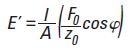 |
Equation 3 |
Where, l refers to the immediate gage length, and A refers to the fiber cross-sectional area. The CDA allows the measurement of the fiber’s dynamic modulus across the entire range of strain during an experiment.
Experimental Method
At North Carolina State University, bicomponent fibers with varied volume percentages of the core and sheath components were prepared. The stronger sheath component has a lower melting point as opposed to the core, to make it suited for thermal binding purposes in nonwovens. However, the core’s elastomer component provides the fibers’ highly elastic nature. Separate concentric sheath-core fibers with 20, 40, 50, 60, 80 and 100 volume% sheath were defined during this study. Optical micrographs of the cross section of bicomponent fibers with three varied sheath-core ratios are shown in Figure 2.
Separate fibers of individual sheath-core ratio were placed on dense paper-based card templates. A caliper was used to determine the gage section of individual fiber samples, and an optical microscope was used to determine the fibers’ cross-sectional areas. The template was later placed on the KLA T150 nanomechanical UTM (Figure 1) using template-grips, followed by clipping the template’s sides to liberate the fiber for testing purposes. Prior to testing, the micro-positioner is utilized to guarantee the correct alignment of the fibers. Testing was done to four fiber specimens of individual sheath-core composition.
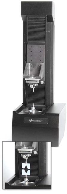
Figure 1. The KLA T150 nanomechanical UTM. Inset shows a card template, containing an individual fiber, mounted on the T150.
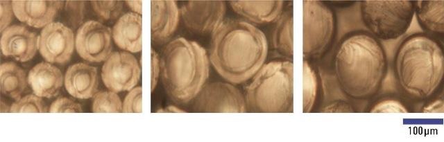
Figure 2. Optical micrographs of the sheath-core bicomponent fibers with 80 vol% sheath (left), 50 vol% sheath (middle) and 20 vol% sheath (right).
Tensile testing of separate bicomponent fibers was done by using the standard Toecomp CDA, together with CDA. The tests were carried out with a strain rate of 1 x 10⁻²s-1. During the course of each test, the CDA was carried out using a 4.5 mN harmonic force at 45 Hz frequency.
Results and Discussion
Figure 3 shows a standard quasi-static stress-strain curve for fibers that contain 100% of the sheath component. It shows three clear deformation regimes - I, II and III – highlighted by vertical dashed lines.
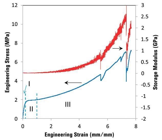
Figure 3. The engineering stress-strain curve, along with the continuous evolution of dynamic storage modulus, for the fiber containing 100 vol% sheath component. Vertical dashed lines represent different regimes of deformation.
This is a predicted behavior because of the polymer’s semi-crystalline nature. Regime I shows uniform elastic behavior, while the amorphous regions align again with the crystalline molecules present in regime II. In regime III, the proportion of aligned polymer chains in the fiber begins to rise, increasing the fiber’s stiffness.
The continuous dynamic storage modulus measurements made during the same experiment (right Y-axis on Figure 3) validates this behavior. The original storage modulus value corresponds well with the Young’s modulus quantified from the quasi-static stress-strain curve. Conversely, in the regime III, the storage modulus begins to increase considerably. A huge deformation of the sheath component can be seen prior to failure. At extremely high strains, the sudden load reduction is stochastic in nature and is attributed to the initiation of failure in the fibers.
The quasi-static engineering stress-strain curves are shown in Figure 4a to 4e, together with the dynamic storage modulus measurements for 80, 60, 50, 40 and 20% sheath bicomponent fibers, in that order. After comparing the curves shown in Figure 4, it can be seen that the load bearing component in these fibers is the sheath. Also, the original dynamic storage modulus values for each fiber are analogous to the quasi-static Young’s modulus measurements. In addition, it is also clear that the extent of increase in the dynamic modulus with strain decreases with the sheath’s decreasing volume. Table 1 shows the fibers’ diameter together with the relative Young’s modulus and tensile strength.

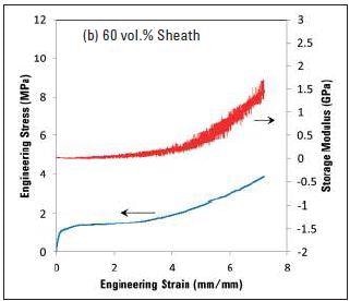
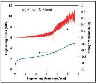
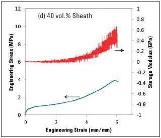
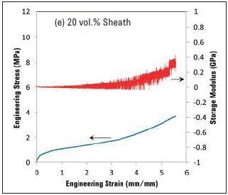
Figure 4. The variation in engineering stress and dynamic modulus with increasing strain for bicomponent fibers with different volume fractions of the sheath. Note the decrease in the magnitude of change in dynamic storage modulus with decreasing sheath content.
Table 1. Tensile properties of sheath-core bicomponent fibers with different volume fractions of sheath
| Fiber |
Average Diameter (µm) |
Young’s Modulus (MPa) |
Tensile Strength (MPa) |
| Pure Sheath |
98 |
40±5 |
7.0±0.3 |
| 80 vol% Sheath |
102 |
35±5 |
6.0±1.0 |
| 60 vol% Sheath |
95 |
20±5 |
4.0±0.5 |
| 50 vol% Sheath |
105 |
16±7 |
3.7±0.7 |
| 40 vol% Sheath |
102 |
12±2 |
3.9±0.6 |
| 20 vol% Sheath |
105 |
8±2 |
4.1±0.3 |
Figures 5a and 5b respectively show the difference in Young’s modulus and tensile strength of the bicomponent fibers with the varied volume fraction of the sheath. The Young’s modulus reduces from approximately 40 MPa for pure sheath component to roughly 8 MPa for just 20 volume% sheath.
The analogous decrease can also be seen for tensile strength, but within 60% sheath, the tensile strength turns out to be nearly constant, regardless of the amount of core or sheath in the fiber. Figure 5 indicates that the material’s modulus is considerably affected by an increased amount of core component. This agrees with the change in dynamic storage modulus shown in Figure 4.
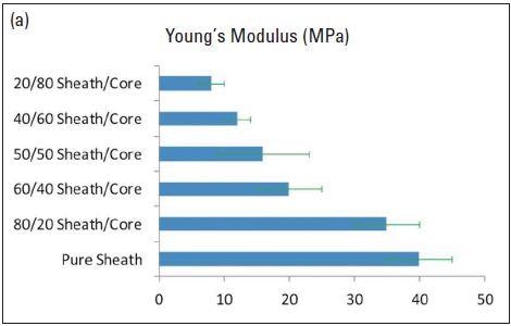
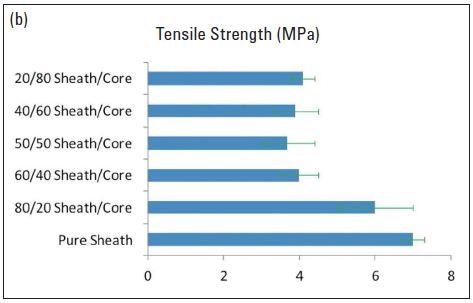
Figure 5. Variation in Young’s modulus (a), and tensile strength (b) of the bicomponent fibers with different volume fraction of the sheath.
Conclusion
The KLA T150 nanomechanical UTM is used to characterize bicomponent fibers with varied volume fractions of core and sheath. This is done to measure their quasi-static and continuous dynamic behavior. The sheath component in these fibers has higher tensile strength and modulus in comparison to the core. Reducing the sheath volume fraction in the fibers can affect the material‘s dynamic modulus and quasi-static properties; however, it does not appear to considerably affect the bicomponent fibers’ tensile strength. To measure the accurate underlying deformation mechanisms, each component needs to be further defined.

This information has been sourced, reviewed and adapted from materials provided by KLA Corporation.
For more information on this source, please visit KLA Corporation.