Thermal Barrier Coatings (TBCs) are multi-material, multi-layer systems that are used to provide thermal insulation and oxidation resistance for underlying structural components.1

Image Credit: KLA Instruments
Event link for details and registration: https://kla-tencor.zoom.us/
Typically, TBCs are made up of (1) an intermetallic bond coat - generally, an MCrAlY alloy, where M = Ni, M=Co or both; (2) a porous ceramic top coat like yttria-stabilized zirconia (YSZ); and (3) a thermally grown oxide (TGO) layer which during high-temperature operation forms at the interface between top coat and bond coat.
To add to this complexity, different microstructural features like porosity, the interface between layers, cracks, and the splat boundaries for thermal sprayed coatings, can also co-exist in TBCs.
Furthermore, material degradation such as aluminum depletion in the bond coat, growth of TGO at the bond coat-top coat interface, and densification of the top coat occur with time and temperature because these coatings often weather extreme environments.2
These degradation mechanisms can operate simultaneously whilst in operation and can instigate changes in its composition and/or microstructure.3 Figure 1 depicts a cutaway view of an aircraft engine, which reveals the variation in pressure and temperature through the airflow path.
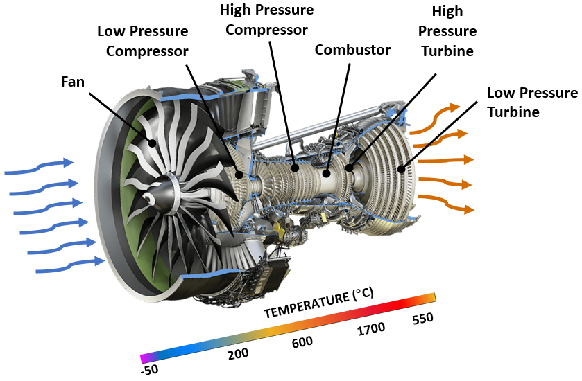
Figure 1. Cutaway view of a GE9X commercial aircraft engine4 showing variation of temperature and pressure through the airflow path. Image Credit: GE Aviation
There is a strong case for applying nanomechanical analysis techniques to the study of TBCs, given the complexities inherent to TBC systems and the advantages of emerging material characterization techniques, such as high-speed mechanical property mapping. This, therefore, facilitates the study of the temporal and spatial properties in respect of the different TBC layers.5
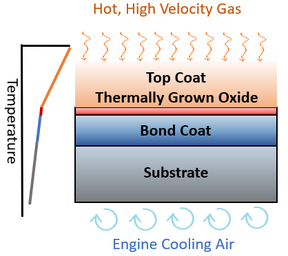
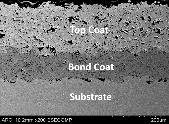
Figure 2. (a) Schematic illustration of the multilayer, multifunctional nature of the thermal-barrier coating system, and (b) cross-sectional scanning electron microscopy image of a TBC. Schematic reprinted from MRS Bulletin Oct 2012. Image Credit: KLA Instruments
Experimental Method
The TBCs in this method were tested using a KLA InstrumentsTM Nano Indenter® employing NanoBlitz 3D - a high-speed mapping technique where each indent typically takes less than a second. The time taken for surface approach, surface detection, loading, unloading and positioning of the sample for the next indentation are all included in the measurement time.
For the bond coat, top coat and bond coat-top coat interface regions of as-coated and thermally-cycled samples, maps of different sizes (typically containing more than 10,000 indents) were generated.
The hardness and elastic modulus for every indent was calculated using the standard Oliver-Pharr method after performing an area function calibration on fused silica samples and correcting for load-frame compliance.6
Results and Discussion
One of the most vital regions of the TBC is the bond coat-top coat interface. The major microstructural variations and their consequent mechanical property variations occur in this region during operation, which ultimately impacts the thermal cyclic life of the TBC.
The formation of a thermally grown oxide (TGO) layer is the most significant event at the bond coat-top coat interface.7 As a result of a reaction between the ingressive oxygen (through the top coat) with inter-diffused aluminum (from the β-NiAl of the bond coat) at high temperatures, TGO is formed.
It is now known that having a contiguous, dense layer of TGO with a parabolic growth rate prevents further oxidation of both the bond coat and the underlying substrate. However, this layer causes severe strain incompatibilities and mismatch stresses beyond a certain critical thickness, which causes the TBCs to become progressively damaged and, ultimately, to delaminate.8,9
It is, therefore, extremely important to determine the local elastic modulus in the TGO. However, given that the optimal TGO thickness is normally on the order of several microns, there has been no reliable local mechanical property measurement when it is sandwiched between the bond coat and top coat.
In the case of the bond coat, high speed mapping at the micron length scale demonstrates that it is now possible to measure the mechanical properties of the TGO.
In FIgure 3, the microstructure (top row), hardness map (middle row) and elastic modulus map (bottom row) at the bond coat-top coat interface are shown for both the as-coated state and after 5, 10 and 100 thermal cycles.
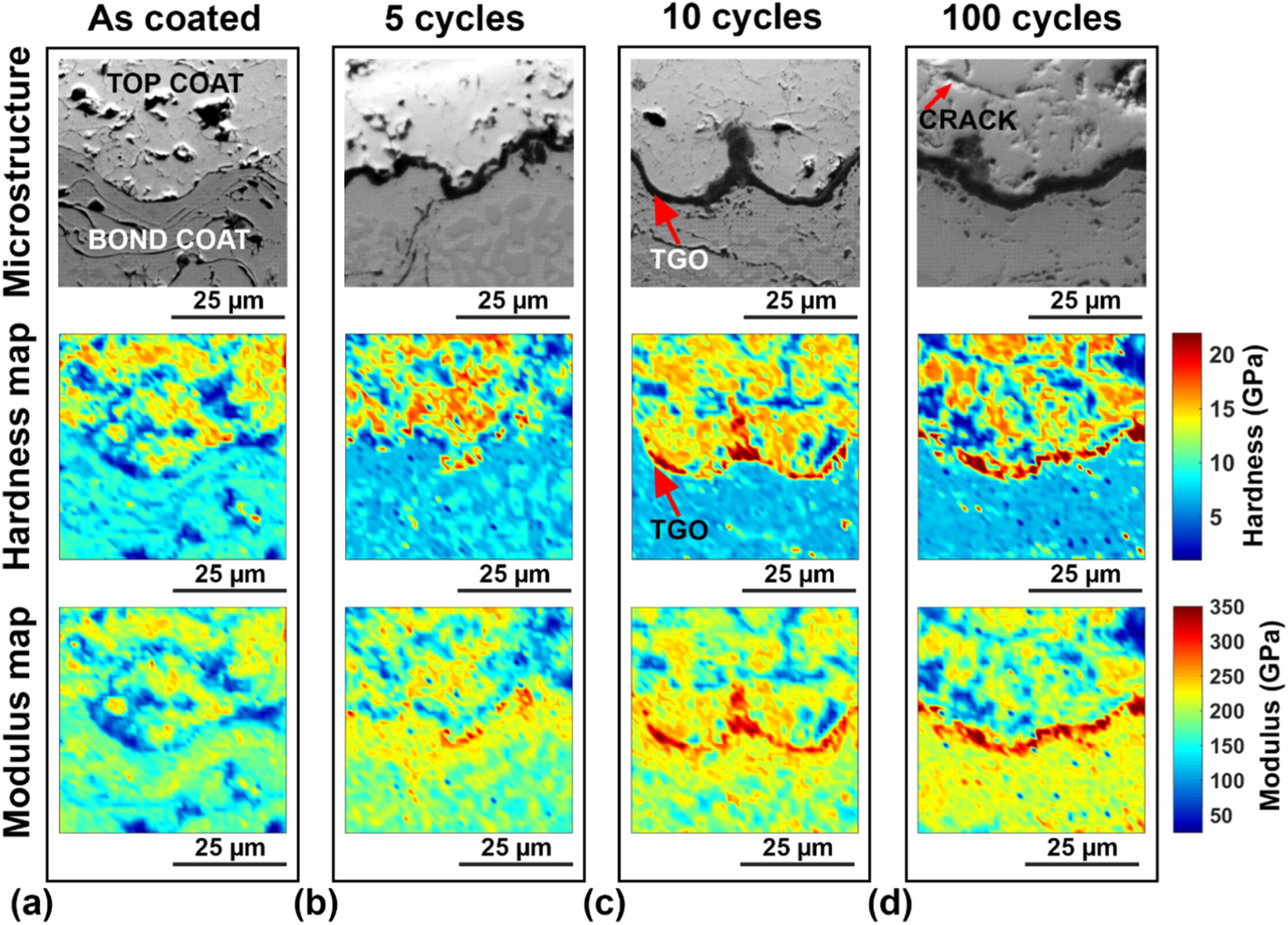
Figure 3. Cross-sectional SEM micrographs and the corresponding hardness and elastic modulus maps at the bond coat-top coat interface show TGO growth for (a, first column) the as-coated state; (b, second column) after 5 thermal cycles; (c, third column) after 10 thermal cycles; and (d, fourth column) after 100 thermal cycles. Image Credit: KLA Instruments
Undulations that are typical of plasma spray coatings are shown at the interface. The TGO (dark region at the interface) can be observed at five thermal cycles, and the thickness of the TGO increases with thermal cycling, as is shown by a comparison of the microstructure of the as-coated and thermally cycled samples.
A similar trend is shown by the corresponding hardness and elastic modulus maps, in which the TGO is identifiable by the higher hardness and elastic modulus regions at the interface. An interesting phenomenon to note is that a parabolic behavior is shown by the thickness of the TGO measured from the maps, which has in the past been observed in microstructural studies.10,11
The depletion of the β-NiAl phase, in addition to the growth of TGO with an increasing number of thermal cycles, acts as an aluminum source on the bond coat side and can be observed from the microstructure and the hardness maps.
One of the primary driving forces for the development of mismatch stresses is the difference in elastic modulus due to the growth of the TGO. As shown in Figure 3, these stresses can generate the production of microcracks in the top coat just above the interface, micrograph (d), for the case of the sample subjected to 100 thermal cycles.
The maps also capture the reduction in hardness and elastic modulus in the cracked regions.
To summarize, the NanoBlitz 3D high speed mapping method can be used to measure the local mechanical properties at the interface of different layers of a coating and for the specific case of a bond coat-top coat interface of a TBC. Measurement of local elastic properties is facilitated by this technique, which is ideal for use in finite element analysis (FEA), specifically for the simulation of delamination of TBCs subjected to thermal cycling.
The high-speed mapping data must be deconvoluted to determine phase-level information of the mechanical properties of the various layers in the TBC. The spatial information about the phases after deconvolution is retained by the clustering algorithm used in this work, which facilitates the reconstruction of a phase map from the mechanical property map.
Furthermore, an expected range of output is not required by the clustering algorithm, which is often required for curve fitting procedures.
Figure 4 shows the deconvoluted map obtained from the hardness map and the microstructure for the case of a sample subjected to five thermal cycles.
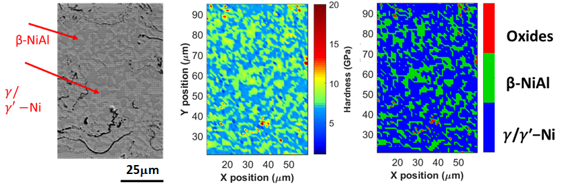
Figure 4. (a) Microstructure, (b) hardness map, and (c) deconvoluted hardness map of the bond coat after five thermal cycles. Image Credit: KLA Instruments
It can be seen from the deconvoluted hardness map in Figure 4c that the property map in Figure 4b has been separated into three distinct clusters based on the hardness data, which in this case are (1) β-NiAl, (2) γ/γ′-Ni and (3) oxides due to internal oxidation.
To represent the mean and standard deviation of the corresponding phases, the mean and standard deviation of the data points in each cluster can be assumed. Please refer to reference5 for more detailed information on data deconvolution.
Conclusions and Summary
In conjunction with the NanoBlitz 3D high speed mapping technique, a KLA Instruments Nano Indenter was utilized to investigate thermal barrier coatings – and specifically the bond coat-top coat interface.
Even at the interface between the various layers of TBC and in the porous top coat, an excellent correlation was found between the local mechanical properties at the micrometer length scale and microstructure.
When it comes to microstructure-based finite element analysis, the phase-level properties obtained from this analysis can be readily used. At the same time, the development of data-driven models for predicting the residual life of TBCs is facilitated by the large data sets obtained through extensive mapping.
References and Further Reading
- D.R. Clarke, M. Oechsner, N.P. Padture, “Thermal-barrier coatings for more efficient gas-turbine engines,” MRS Bulletin 37 (2012) 891–898, https://doi.org/10.1557/mrs.2012.232.
- V. Kumar, K. Balasubramanian, “Progress update on failure mechanisms of advanced thermal barrier coatings: a review,” Progress in Organic Coatings, v. 90 (2016) 54–82, https://doi.org/10.1016/j.porgcoat.2015.09.019.
- B.G. Mendis, B. Tryon, T.M. Pollock, K.J. Hemker, “Microstructural observations of as prepared and thermal cycled NiCoCrAlY bond coats,” Surface Coating Technology 201 (2006) 3918–3925, https://doi.org/10.1016/j.surfcoat.2006.07.249.
- https://www.geaviation.com/commercial/engines/ge9x-commercial-aircraft-engine.
- B. Vignesh, W.C. Oliver, G. Siva Kumar, P. Sudharshan Phani, “Critical assessment of high speed nanoindentation mapping technique and data deconvolution on thermal barrier coatings,” Materials & Design, vol. 181 (2019), 108084; https://doi.org/10.1016/j.matdes.2019.108084.
- W.C. Oliver, G.M. Pharr, “An improved technique for determining hardness and elastic modulus using load and displacement sensing indentation experiments,” Journal of Materials Research, vol. 7 (1992) 1564–1583, https://doi.org/10.1557/JMR.1992.1564
- N.P. Padture, M. Gell, E.H. Jordan, “Thermal barrier coatings for gas-turbine engine applications,” Science, vol. 296 (2002) 280–284, https://doi.org/10.1126/science.1068609.
- K.S. Chan, “A mechanics-based approach to cyclic oxidation,” Metallurgical and Materials Transactions A, vol. 28 (1997) 411–422, https://doi.org/10.1007/s11661-997-0142-2.
- C.J. Li, H. Dong, H. Ding, G.J. Yang, C.X. Li, “The correlation of the TBC lifetimes in burner cycling test with thermal gradient and furnace isothermal cycling test by TGO effects,” Journal of Thermal Spray Technology, vol. 26 (2017) 378–387, https://doi.org/10.1007/s11666-017-0530-0.
- D.-J. Kim et al., “Evaluation of the degradation of plasma sprayed thermal barrier coatings using nano-indentation,” Journal of Nanoscience and Nanotechnology, vol. 9 (2011) 7271–7277, https://doi.org/10.1166/jnn.2009.1786.
- J. Toscano, R. Vaßen, A. Gil, M. Subanovic, D. Naumenko, L. Singheiser, W.J. Quadakkers, “Parameters affecting TGO growth and adherence on MCrAlY-bond coats for TBCs,” Surface Coating Technology vol. 201 (2006) 3906–3910, https://doi.org/10.1016/j.surfcoat.2006.07.247.

This information has been sourced, reviewed and adapted from materials provided by KLA Instruments™.
For more information on this source, please visit KLA Instruments™.