|
To meet the demands of ultra-precision positioning and scanning, a series of precision positioning mechanisms have been developed recently at Queensgate Instruments, which combines Queensgate’s piezoelectric and NanoSensor technologies into multi-axis positioners which have the ability to position with sub-nanometric accuracy. In this paper the design philosophy and some of the technologies used in the development of these mechanisms are introduced and discussed to explain how a metrological capability at the nanometer or even sub-nanometer level can be achieved. Some initial results are included, in which stages with 0.01 % linearity error, sub-nanometer hysteresis, very low angular parasitic motions and good dynamic response, etc. are demonstrated.
In recent years, as the result of rapid developments in various fields of precision engineering, there has been a big increase in the need for precision positioning and scanning systems capable of nanometer or, sometimes, even sub-nanometer resolution and repeatability. This trend is expected to grow, requiring new design concepts and techniques for exploration of more novel devices to meet the demands of various applications. For example, wafer steppers are making silicon chips with line widths down to 200 nm; Scanning Probe Microscopes are used to establish how well such chips are made; and the introduction of M-R head technology allows 5 Gigabyte disks to become the norm. These machines, and the machines which make these machines, combine advanced optical design with advanced motion control technology, which can position components to an accuracy of a nanometer or better.
To meet the challenge of these developments, Queensgate Instruments is developing an ultra-precision positioning technology which combines Queensgate’s piezoelectric and NanoSensor technology into multi-axis positioners with the ability to position with sub-nanometeric accuracy. This system is composed of a series of stages, called NanoMechanisms, including single axis stages, x-y stages and tilting stages etc. The combinations of these stages can provide three, four, five or six degree of freedom positioning units.
Design Philosophy of Nanometer Precision Mechanisms (NanoMechanisms)
Mechanisms
Piezo-electric devices have the potential to move stages with the resolution and stiffness required for nanometer precision positioning. However, because piezo-electric devices are non-linear and exhibit hysteresis, an external sensor is required to control their position. The capacitance micrometer is ideally suited to this task, being small and simple with an intrinsic resolution capability that is effectively infinite. To achieve a pure single axis motion, a flexure guiding mechanism is used, which implements constraints to any off axis motions and combines piezo actuator and sensor together to form an integral stage system. The flexures are normally monolithically cut into the stages using EDM machining, which gives a very high precision in performance.
Figure 1 is a typical closed loop control block diagram of this kind of system. In the diagram, the motion measured by the sensor is fed back to the controller, which moves the stage to minimise the difference between the sensed motion and the command. In this case, the positioning precision in the metrology loop is mainly determined by the capabilities of the sensor and controller.
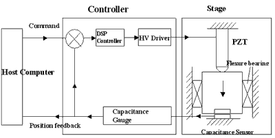
Figure 1. Block diagram of a single axis control system of NanoMechanism.
Capacitance Position Sensor
The NanoSensor is a highly linear capacitance sensing device with linearity errors of < 0.02 % over its specified operating range (normally between 100 ~ 500 µm). Operating over a reduced range linearity errors of below 0.01% are possible. The NanoSensor has a positional noise level in normal operation of < 0.005 nm.Hz-½ (RMS) and can be fabricated from very stable materials like Super Invar or Zerodur. It is non-contact and free from hysteresis. It also has the advantages of being very compact, simple, cheap, and with no power dissipation at the point of measurement. Thus it is well suited to the accurate measurement of extremely small displacements.
Controller
When designing a system with 0.1 nm resolution and 100 µm range the ability to access that range digitally under computer control is normally extremely difficult, since it is a dynamic range of 1 part in a million, or 20 bits. To address this problem Queensgate have developed a Digital Signal Processor (DSP) based control system, which has an intrinsic resolution of more than 21 bits, and is addressable digitally. It should be noted that this far exceeds the resolution of most A/D and D/A converters available presently and is below the noise levels in most applications. Advanced digital PID control algorithms have been used in the system. A block diagram of the closed loop controller is shown in Figure 2. The system response can be improved by introducing the proportional and differential terms. Velocity feedback (differential term) can greatly help in damping out mechanical resonances, reducing settling times. The working bandwidth can be controlled by computer and loop parameters be defined by the user for performance optimisation.
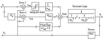
Figure 2. Block diagram of PID closed loop control.
Using such a controller it is possible to measure the non-linearity and to compensate for it. Furthermore once parasitic angular motions in such mechanisms have been characterised it is possible to compensate for them in a complex multi-axis system. The linearity errors can be fully compensated to < 0.02 %. Below that the measurements are normally limited by the intrinsic linearity of the calibration systems.
The use of this compensating technique is very important to achieve a metrological capability at the nanometer level. It is obvious that within the control loop the sensor is not absolutely linear, so the system linearity can be further improved by software compensation. Ideally, the mechanism should exhibit pure orthogonal motions - that is, an x-y device must only have degrees of freedom along the x and y axes. In reality, there exist uncontrolled (parasitic) motions arising from distortion due to internal forces and manufacturing limitations. The errors from these parasitic motions have been minimised by optimising the mechanical design and can be reduced further by the compensation technique. Note that the parasitic errors can only be compensated if they are predictable, i.e. the parasitic motions have to be not only measurable but also repeatable.
Design Concepts and Considerations
Coordinate System
First it is necessary to define the co-ordinates used to describe positions. The obvious system to use for positioning stages is an orthogonal Cartesian Co-ordinate system. With this one can define a position with its X, Y, Z co-ordinates and an arbitrary rotation as components of rotation about the X, Y and Z axes, as shown in Figure 3. More usefully one can describe a movement as a change in the X,Y and Z co-ordinates. Rotations are described with respect to the X, Y and Z axes in a right-handed sense. The terms pitch, roll and yaw are often used when talking about the rotations. These terms are useful when describing parasitic rotations caused by a linear motion, but great care must be taken as they are referred to the direction of motion rather than a defined axis system. For an aeroplane in flight, a rotation about an axis drawn from wing tip to wing tip is pitch; a rotation about an axis drawn down the length of the fuselage is roll and a rotation about a vertical axis is yaw. In the defined Cartesian system if the 'plane' is flying along the positive X direction θ is pitch, γ is roll and φ is yaw.
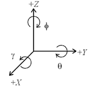
Figure 3. Coordinate system.
Positioning Accuracy: The Concept of Trueness
To move a stage, a position command is sent to the controller by a computer. The motion is produced by a piezo actuator and monitored by a sensor. Using the feedback signal, the controller moves the stage to minimise the difference between the sensed motion and the command. How small the difference can be is mainly determined by the controlling ability of the system and can be interpreted as how precisely the stage can be positioned. It is obvious that the positioning precision will be mainly affected by resolution (noise level), reproducibility (drift and hysteresis) and mapping error (high order error of mapping) of the system. Moreover, if the stage motion is measured with an external measuring device which is assumed to be a perfect system, there will be a difference between the commanded position and desired position: how close they are is defined as positioning trueness. Therefore, the final positioning accuracy should be determined by both the positioning precision and the positioning trueness, as shown in Figure 4. How these are dealt with in NanoMechanisn design will be discussed in following sections.
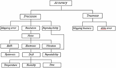
Figure 4. Measurement Accuracy.
Resolution and Noise
The resolution of measurement or positioning is directly related to the noise level of the system. A peak to peak noise level is not easily measured or interpreted, since with any noise distribution you can get a large deviation if you wait long enough. Therefore the rms value is normally used which can be measured with standard equipment. The noise amplitude distribution is important when looking at resolution. Usually Gaussian noise dominates and in this case the rms is equivalent to the standard deviation, sigma. 68.3 % of samples taken will be within one sigma of the mean value. That means there is a 68.3 % chance of resolving two features which are a distance of two sigma of the noise apart, as shown in figure 5, (or 99.7 % chance of resolving two features which are six sigma apart).
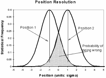
Figure 5. Resolving two positions.
The noise power spectrum is a most important piece of information. It can show up the underlying sources of noise - such as mains pick up, which is localised at 50 or 60 Hz. Figure 6 demonstrates a measurement of the noise power spectrum of the DSP based NPS3000 controller. This shows a noise level of < 10 pm.Hz-½. In the test, the NPS3000 controller is used to control a single axis stage, (the NPS-Z-15B), in closed-loop mode with a stage working bandwidth of 100 Hz. The noise signals plotted are from the HV drive voltage applied to the piezo actuator. 50 Hz mains pick up can be seen clearly although at a very low level.
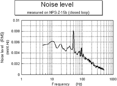
Figure 6. Noise spectrum of NPS3000 controller.
The noise in the NanoMechanism system is, in general, composed of sensor noise, piezo drive noise, mechanical noise and acoustic noise. Sensor noise will be interpreted by the control loop as a command and thus becomes actual displacement noise. The feedback signal from the sensor is used to generate a drive voltage to be applied to the piezo actuators. Piezo drive voltage noise will be introduced in this process and contribute to the stage positioning noise. The effect of this noise can be detected by the sensor and, therefore, at least partially servoed out. The ability of the system to servo out the drive noise depends on the bandwidth set: the higher the bandwidth the better the contribution is servoed out. External mechanical inputs such as ground vibration and acoustic noise will also cause the stage to move. The effects of these inputs can be minimised by increasing the stiffness of the stage. It can also be servoed out if the system bandwidth is sufficiently high. For the control system NPS3000 the measurement bandwidth can be set up to 12 kHz and closed loop bandwidth 2 kHz which is normally dominated by the dynamic characteristics of stage mechanisms.
Linearity and Mapping
In an ideal world, a stage should be perfectly linear. The world is almost ideal but not quite. In practice the linearity of the capacitance sensor can be affected by many factors such as the thickness of nominal gap (or stray capacitance) and non-parallelism of the electrode surfaces, etc [1]. In order to know what the actual motion or position of the stage is and thus to apply linearity compensation, the system has to be calibrated against an external measuring device with high accuracy. The command position, xc, which represents the position measured by the internal sensor and the actual position, xp, can, to a certain extent, be related with a mapping function expressed as xp = f(xc). The simple form of the mapping function is a power series
 (1) (1)
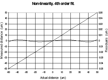
Ideally a0, a2, a3, a4...would be zero and a1 unity; then the sensor scale factor, a1, is the linear factor describing the relationship between the actual stage position as measured by a hypothetically perfect accurate position sensor and the position measurement fed back to the user's computer. The mapping trueness is characterised by the set of errors on the individual 'a' coefficients. When the mapping function is first order (a straight line), the mapping error becomes the scale factor uncertainty. The residual between the actual position and a best fit straight line for the measurement gives linearity error (normally we define the linearity error as ½ pick to pick residual from the linear best fit). As an example, a linearity error of 0.05 % in a 100 µm range device results in a 50 nm absolute position uncertainty between the 0 µm position and the 100 µm position when a linear approximation is made, as shown in Figure 7 (a). Usually for NanoSensors the deviation from linearity is roughly parabolic and in some systems this is easy to compensate for electronically without involving the DSP. The result of compensating one, slightly imperfect, parabola with another is usually an S curve of much lower amplitude so the mapping error is much lower, as shown in Figure 7 (b). This is equivalent to using the a1 and a2 terms of equation 1. If one were to use the higher order terms, an even better result could be achieved. This can be done easily in microprocessor based sensor systems or externally in the user's computer. It has been found that there is little to gain in going higher than fourth order, see Figure 7 (c).
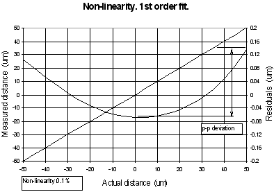
(a)
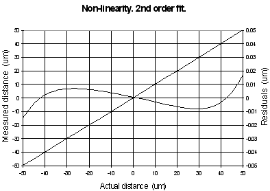
(b)
(c)
Figure 7. Mapping error and linearity.
Parasitic Motions and Errors
Parasitic motions in stages can be identified as either angular: rotation about x, y and z axes; or linear: out of plane motion, non-orthogonality and crosstalk; and will introduce unexpected positioning errors. The parasitic motions caused by distortions of the stage body can be minimised by careful design and structure parameter optimisation. In the constrained axes the stiffness should be designed to be as high as possible, and as low as possible in the axis of motion. This is achieved in the NanoMechanisms by properly arranging the flexure pattern and choosing the flexure parameters carefully. However, the flexure design is sometimes limited by the system resonant frequency which, because of mode coupling, requires the stiffness in all directions to be high. Finite element analysis FEA can be used to predict local and global distortions and hence the structure can be properly optimised to decouple the forces or make the inevitable distortions cancel each other. If these parasitic motions are predictable then they can be compensated. Note that these motions are a function of the stage position, but are not necessarily linear, leading to complex topography. Any hysteresis in motion makes the prediction very hard - if not impossible. For this reason, the force changes in the system must be highly linear and repeatable. Friction is always a source of hysteresis, due to the changing direction of the force.
When specimens are mounted on to a NanoMechanism, Abbe errors have to be considered carefully due to the parasitic angular motions. Small angular errors can have a large affect at the nanometer level: for example, a tilt of just 1 µrad with an offset of 1 mm gives a 1 nm position error. To reduce this effect, specimens should be positioned as close as possible to the measuring axes of the sensors. For example, in an x-y-z three axis NanoMechanism system the specimen holder is located at the point which is co-incident with the sensor measuring axes, as shown in Figure 8. The effects of rotation errors of the x-y stage can thus be minimised.
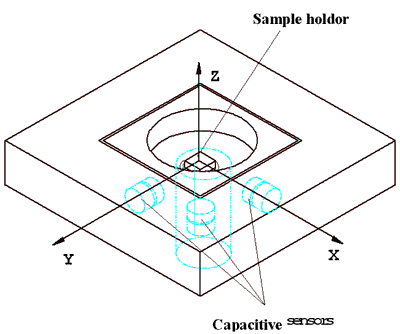
Figure 8. 3D Nanomechanism.
The linear parasitic motions such as non-orthogonality or crosstalk are mainly affected by manufacturing tolerances and the distortions of stage frame if the frame is used as sensors’ datum. The axes of two pairs of sensors in the x-y stage have to be very orthogonal to each other and co-incident to the moving axes of the platform. Using modern manufacturing technology the deviation from orthogonality of the sensor axes can be generally controlled within 0.5 mrd which gives an orthogonality error of 0.5 nm/µm (i.e. 0.05 %) in the x-y plane.
By kinematic mounting, the position reference becomes traceable and the distortions from thermal expansion and driving force can be decoupled. This is important for the stage to have metrological capability at the nanometer level. Even for a Super Invar stage of the size of 100 x 100 mm, a 1oC temperature change will cause 30 nm change in dimension ( = =  /oC). The stage frame bending caused by the driving force is typically in the range of tens to hundreds of nm[2]. Without kinematic mounting a position uncertainty of about those same magnitudes might be introduced into the system. /oC). The stage frame bending caused by the driving force is typically in the range of tens to hundreds of nm[2]. Without kinematic mounting a position uncertainty of about those same magnitudes might be introduced into the system.
Dynamic Characteristics
Aside from the metrology and accuracy of motion, the dynamic performance of the system is also important because the stability and speed are critical to many applications. Ideally there would be no phase lag between command and position, and the mechanism would respond perfectly to a step input - no rise time, over shoot, or settle time.
For a linear, second-order, damping-free mechanical system, the resonant frequency is determined by system stiffness and mass. In an optimally designed mechanism, the stiffness is usually dominated by the stiffness of piezo stacks in its translation axis. For a stage with motion amplification, the effective stiffness of the piezo actuator will be reduced as ke = kp/G2, where kp is the stiffness of piezo and G is the amplification. Reducing the mass can increase the system resonant frequency. However, as the mass of the platform decreases the stage performance becomes more sensitive to the influence of the load mass, i.e. the resonant frequency will drop down rapidly as the mass of the specimen increases. Dynamic properties of the system can also be improved through other approaches such as introducing a proper damping material or using advanced servo control techniques. In instrumentation, the design specifications often use the criterion of settling time, defined as the time required for the system to settle within a certain percentage of the input. For NanoMechanisms, like other instruments, settling time is a more direct description of the dynamic performance than resonant frequency. For a piezo driven NanoMechanism, the settling time consists of the slewing time and the time taken for the resonant oscillations to decay. The former is dominated by the slew rate which is determined by the capacitance of the piezo stacks and the current drive capability of the drive electronics. For second order systems the requirement typically specifies a maximum delay before the output reaches within 2 % of its final value after a step input change, which takes a duration of approximately four time constants (4τ=4/ξωn), where τ is time constant, ξ damping factor and ωn resonant frequency[3]. From this it can be seen that the system response can be improved by increasing both the resonant frequency and the damping factor. Normally, flexure hinge stages are highly resonant with very low damping factors. Therefore, extra damping will be very helpful and can effectively reduce the decay time, but only if it can be introduced without friction, since this can cause hysteresis. If this is done within the control algorithm, then no friction will be introduced.
Materials
Thermal properties of construction materials are often the main concern for both design and use of precision instruments. In normal use, all mechanical devices encounter heat inputs caused by environmental temperature change, power dissipation in actuators, operator handling and so on. The direct effect of the thermal disturbance is thermal expansion which will cause dimension change of mechanical components, resulting in the loss of instrument accuracy. The dimensional change of a material due to a change in temperature is characterised by its Coefficient of Thermal Expansion (CTE), which varies tremendously with different materials. In general, to reduce the thermal effect, construction materials with minimal thermal expansion coefficient should be used. However in some cases low thermal expansivity is not as useful as the close expansivity match between the device and its mounting. Moreover, corrections to cope with thermal expansion are possible through control methods: the temperature can be measured and used to provide a correction. Another problem is thermal gradients. They cause structure distortion, for which compensation is not possible. To avoid the effects of thermal gradients, the materials can be chosen either with low thermal conductivity, such as Super Invar and Zerodur, or with high conductivity, such as Aluminium, where the system reaches thermal equilibrium quickly. To reduce the effects of the environment many precision devices are deliberately designed to be small.
Also the mechanical properties of materials have to be carefully considered. For example, the ratio of strength and Young’s modulus, /E, limits the maximum range which can be achieved by flexure mechanisms. However, low Young’s modulus may not be able to provide a sufficient stiffness for the NanoMechanism or its frame, which is sometimes used as the metrological datum. Further, local contact stiffness between the mechanism and its actuators has a direct effect on the resonant frequency of a mechanical system - the resonant frequency can drop down because of insufficient contact stiffness. Also the mass of material can make a big difference to the dynamic properties of NanoMechanisms. For example the density ratio of Super Invar and aluminium alloys is about 3, so the resonant frequency of an aluminium system can be √3 times higher than that of a Super Invar system if the stiffness of the systems are the same.
Some Examples of NanoMechanism Devices
NPS-Z-15A/B
This is a single-axis linear motion stage which is designed to produce a pure motion along the z axis. The stage has a closed loop range of 15 µm and a typical linearity of < 0.06 % (without compensation) with sub-nanometer resolution. After compensation the non-linearity typically drops down to <0.02 %. A compact flexure mechanism is designed into the stage to decouple the parasitic off axis and tip-tilt motions from the piezo stacks. The tilting errors are measured to be less than 1 µrad over whole range, (without flexure mechanism the tilting errors are normally over 15 µrad). Low hysteresis is another important feature for the stage to achieve nanometer metrological capability. Figure 9 is a typical measurement result of static performance from the stage NPS-Z-15B, which demonstrates a linearity error of 0.01% and a sub-nanometer hysteresis. Most of the specifications were calibrated using a Zygo ZMI 1000 interferometer. However the measurement of sub-nanometer hysteresis becomes difficult using the interferometer – so for those measurements a Queensgate NanoSensor was used. The resonant frequency of the stage is 2 kHz which gives a good dynamic response for most applications when used with NPS3000 controller. A step response is shown in Figure 10.
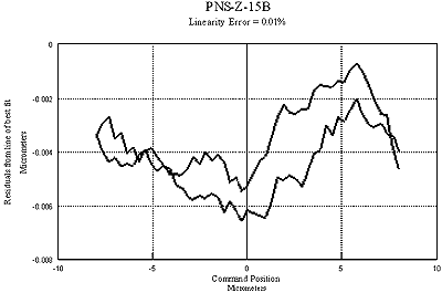
Figure 9. Linearity and hysteresis of NPS-Z-15B.
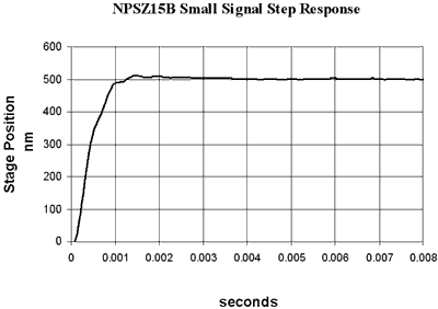
Figure 10. Step response of NPS-Z-15B.
NPS-XY-100A
This is a two-axis linear motion stage with a 40 mm diameter aperture in the middle (convenient for NSOM applications). It has a dynamic range of 100 100 µm with sub-nanometer resolution. By careful design and precision manufacture, the rotational errors about z axis (δγz, δθz) are controlled less than 10 µrad and other rotational errors are insignificantly small over the whole range. The hysteresis was measured as less than 0.01 % of the range. Figure 11 presents a typical measurement result of static performance from the stage NPS-XY-100A. Integral kinematic mounting mechanism helps to relieve the strains induced by internal drive forces and thermal expansion, improving the stability of the system. The kinematic mounting mechanism ensures that the system datum is at the centre of stage platform on which the specimen or the probe is normally located, so that the thermal effect can be effectively decoupled. The stage is made of Super Invar and has a resonant frequency over 300 Hz. By introducing extra damping into the system, a 10 ms settle time for small step response can be achieved, as shown in Figure 12. Combining NPS-XY-100 and NPS-Z-15 forms a 3D positioning and scanning system, as shown in Figure 8, which is ideal for metrological SPM applications.
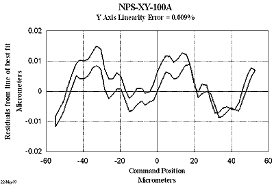
Figure 11. Linearity and hysteresis of NPS-XY-100A.
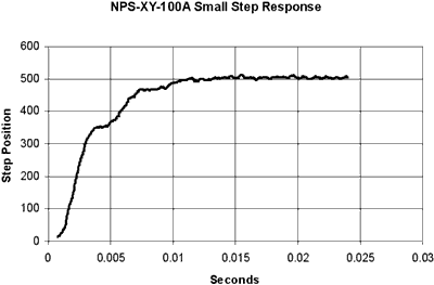
Figure 12. Step response of NPS-XY-100A.
Conclusions
Some of the technologies used in Queensgate’s nanometer precision mechanisms have been introduced and discussed to explain how a metrological capability at nanometer or even sub-nanometer level can be achieved with the NanoMechanisms. Some metrological concepts have been clarified in the way they are used to describe ultra-precision positioning techniques. The design considerations have been discussed with reference to the problems of resolution and noise, linearity and hysteresis, thermal expansion and force distortion, and parasitic motions like non-orthogonality (crosstalk), rotation errors and Abbe errors etc., which introduce positioning errors and uncertainty to the system. Some approaches for avoiding or minimizing these errors were mentioned. This involves both optimised design and advanced compensation techniques. More detailed information is available from Queensgate[3]. A series of NanoMechanisms, ranging from single axis to multi axis stages, have been designed and built. The combination of these stages can provide motions of up to six degrees of freedom with nanometer precision. Initial testing has shown promising results, such as low noise level, sub-nanometer hysteresis, very small parasitic motions, high linearity and good step response. A comprehensive assessment of metrological characteristics is a complicated and long term project, especially for multi axis systems, involving more sophisticated metrological techniques and advanced instruments. Further results will be reported in the near future.
Acknowledgements
The authors would like to express thanks to Graham Jones, Jeremy Russell and Philip Rhead for their help in designing, building and testing these NanoMechanisms.
Reference
1. The Nanopositioning Book, Queensgate Instruments Ltd, 1997
2. P. D. Atherton, Y. Xu and M. McConnell, “New x-y stage for positioning and scanning”, Proceedings of SPIE’s Annual Meeting, Aug. 1996, Denver, USA
3. S. T. Smith and D. G. Chetwynd, Foundations of Ultraprecision Mechanism Design, Gordon and Breach Science Publishers, 1992
|