|
In recent years industry has shown growing interest in linear ultrasonic piezoelectric actuators and ultrasonic drives. Well-known manufacturers of micropositioning systems have increasingly put micropositioning systems driven by ultrasonic actuators onto their product palette.
Piezoelectric ultrasonic actuators make possible systems which are of simple design, and are thus finding wider and wider application in micropositioning systems.
Especially advantageous and cost-efficient systems can be made with ultrasonic actuators having a rectangular piezoceramic plate as resonator and using eigenmodes associated with that shape. Probably the best-known design for such an ultrasonic motor uses what is called a bimodal ultrasonic actuator. Here the piezoelectric plate is excited simultaneously in a flexural mode and in a longitudinal mode. This operating principle, suggested in the 70’s [1], [2] and first exploited industrially by Nanomotion, has proven so effective that actuators using it are encountered in most linear piezomotor micropositioners on the market today. Such actuators are also offerred by PI, both alone and in derived products [3].
Physik Instrumente (PI) GmbH & Co. KG, one of the leading manufacturers of piezoelectric actuators and positioning systems, has for many years been involved in the development and fabrication of ultrasonic piezomotors and positioning systems incorporating them. PI’s newly developed ultrasonic piezomotors are based on excitation of a special eigenmode (2-D standing wave) in a piezoceramic resonator. The wave has two orthogonal vibration components which are coupled. This eigenmode can be excited both in piezoelectric hollow cylinders and in rectangular plates, making possible fabrication of very simple, high-performance rotational [4] and linear motors. In this article, the authors describe the operation of the new ultrasonic piezoelectric plate actuators.
Working Principle and Design of the New PIline Ultrasonic Actuator
Fig. 1 shows the newly developed ultrasonic piezoceramic actuator and the basic design of a translation stage driven by it. The actuator consists of a piezo-ceramic plate of size LxWx0.5L (X, Y, Z), polarized in the Y-direction. The two large faces of the plate are covered by electrodes. On the front are the two exciter electrodes, each covering half of the surface. The rear surface has a single electrode that serves as a common drain. On one long edge of the plate is a pusher, made of aluminum oxide. The slider, the moving part of the motor, is pressed against this pusher.
Figure 1. Piezoceramic ultrasonic actuator (top) and basic design of piezo-actuator-driven translation stage.
Operation of the new piezomotor is based upon asymmetric excitation of the piezoceramic plate in a special resonant mode consisting of a two-dimensional standing extension wave. Because of the asymmetric oscillation, the pusher moves along a straight-line trajectory that is inclined at either 45°-or with mirrored excitation-at 135° to the edge of the actuator. The actuator is excited with a sine wave voltage applied to one of the excitation electrodes while the other electrode floats (the potential on the second electrode could be used in a feedback loop for matching the excitation frequency with the resonant frequency of the actuator). As a result of this excitation, the pusher provides micro-impulses at very high frequency, driving the slider. To change the direction of motion, the other electrode is excited and the first allowed to float. This changes the trajectory of the pusher by 90°, so that it impells the slider in the opposite direction.
Fig. 2 shows the results of harmonic analysis in four specific oscillation phases using a FEM model (finite element method) of the actuator and FEM analysis software from ANSYS. The material properties used were those of the piezoelectric ceramic PIC-181 from PI Ceramic in Lederhose, Germany.
Figure 2. FEM- Simulation.
FEM Simulation
As already explained, the new actuator works based on asymmetric excitation of a two-dimension standing extension wave in a piezoelectric plate. Similar to the designation usually used in the literature for 2-D flexural waves, we call the various modes of this type E(k, l), where “E” indicates “extensional” and k and l are the number of half wavelengths (λ/2) in the X- and Z-directions, respectively. The E(3,1) mode can be excited in a plate (polarized in Y, normal to the faces) if the length-to-height ratio is approximately 2 to 1, L/H≈2:1
With electrodes fully covering the two faces, the mode shape can be described mathematically as follows:
 (1) (1)
 (2) (2)
Where Ux, Uz are the distortional displacements in the X and Z directions at points x, z and time t and A, B, C are material and geometrical amplitude functions.
This oscillation mode is thus described by standing waves in the X- and Z-directions respectively, (Gl (1), (2)).
Fig. 3 shows the results of a modal analysis of a piezoceramic plate with X, Y, Z dimensions of 60x9x28 mm, polarized in the Y-direction (9mm) and with electrodes fully covering the two faces. Fig. 4 shows the amplitude and phase characteristics for points on the top edge of the plate (along the length) as a function of their X position (0 to L along line L in the figure). The phase difference between the X and Z displacements alternates between 0° and 180° as a function of the X position. As a result, the points on a line along the top edge of the plate move along linear trajectories.
Figure 3. E(3,1) Modes in a 60x9x 28 mm3 (L, W, H) piezoceramic plate (a) Deformation. (b) X-oscillation velocity distribution (c) Z-oscillation velocity distribution (FEM simulation).
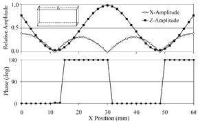
Figure 4. Amplitude and Phase diagram.
The highest oscillation velocities in the Z-direction are found at the center of the long sides (X-coordinate = length/2, Z-coordinate = H). The oscillation velocity in the X-direction at this point is zero, meaning that this midpoint oscillates in a vertical straight line. The resonant frequency of this mode is 62.9 kHz.
Fig. 5 (a) shows a FEM simulation of the oscillation amplitude distribution of the points, as well as a representation of their trajectories, as a function of position along the long side of the piezoceramic plate (Line L in Fig. 4).
Fig. 5 (b) shows the same diagrams, but with measured values, for comparison. To obtain these values, the oscillation behavior of a piezoceramic plate was investigated using a vibration sensor (also of piezoceramic) material. The sensor captures surface vibrations of the plate in two dimensions over a single-point feeler [5].
Figure 5. Displacement motion. (a) FEM simulation; (b) Measurement.
The measurements were carried out on a piezoceramic plate with X, Y, Z dimensions of 60x9x30mm3, polarized in the Y (9mm) direction and with electrodes fully covering the two faces. The resonant frequency is 60.1 kHz (61.6kHz measured value).
To obtain slider motion with the pusher in the center (X coordinate = Length/2, Z coordinate = Height) it is necessary to increase the X displacement at that point, and a mechanism to reverse the phase between the X and Z displacement by 180° must be available. This is accomplished by exciting the X direction standing wave asymmetrically. To do so, the excitation electrode is cut vertically into two electrodes, each covering only half of the XZ surface. During operation, only one of these two electrodes is excited while the other is left to float. Fig. 6 shows the FEM simulation and measured values resulting from this asymmetric excitation of the mode in a 60x9x30mm3 piezoceramic plate. This is the excitation technique used for the newly developed actuator. The diagram shows the reduction of the X amplitudes in the excited side of the plate and their simultaneous augmentation on the other side. In addition, the standing wave in X-direction is shifted toward the excitation electrode, as seen by the shifted node lines (compare Fig. 5 and Fig. 6). The shifting of the X-direction standing wave results in increased X displacement amplitudes at the center of the plate.
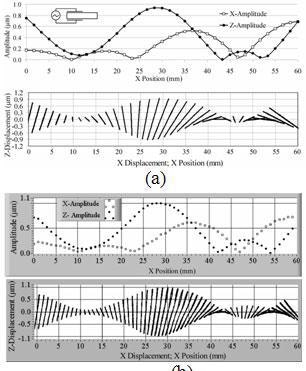
Figure 6. Displacement motion. (a) FEM simulation; (b) Measurement.
PI Linear Motors and Stages with New Actuators
The new actuators are being used in new linear motors and complete linear stages. These actuators make possible construction of very small linear stages with ideal parameters. Fig. 7 shows three such actuators and linear motor and stages in which they are used.
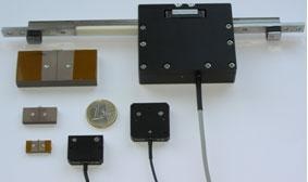
Figure 7. Linear actuators measuring 18x8x3mm, 25x12x4mm, and 60x9x28mm with the corresponding linear motors.
The PIline™ M-661, M-662 stages are driven by a small external driver that converts controller signals into the ultrasonic oscillations required by the piezo actuator. Control is either electronic or through a manual pad. Electronic control is achieved through a PWM drive signal of 12 V. The smallest step is on the order of 50 nm and corresponds to an approx. 10 µs input. These units achieve velocities to 800 mm/s. By varying the length of the input-active period, the step length, and thus the velocity, can be controlled. The translation stages are equipped with integrated high-precision optical linear encoders for closed-loop operation with standard servo-motor controllers. For optimum closed-loop performance it is operated with a PID motion controller that allows setting of the full range of parameters tailored to piezo motor operation.
As an example, Fig. 8 shows the internal layout of a linear motor with a 60 x 9 x 28 mm actuator.
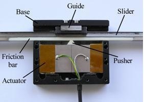
Figure 8. Linear motor with 60x9x28 mm actuator.
Figures 9 to 11 show the main characteristic curves of this motor.
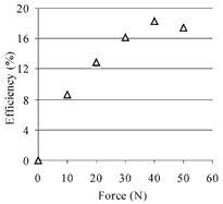
Figure 9. Efficiency vs force characteristic of linear motor with 60x9x28mm actuator.
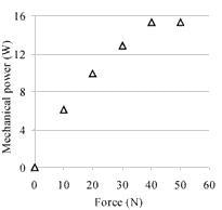
Figure 10. Power vs force characteristic curve of linear motor with 60x9x28mm actuator.
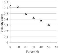
Figure 11. Velocity vs force characteristic curve of linear motor with 60x9x28mm actuator.
This linear motor has the best performance of any built to date. Its maximum power output is 16 W, and the efficiency reaches 18%. The maximum (open-loop) velocity is 600 mm/s, and the maximum force developed, 60 N. The nominal voltage applied to the actuator is 200Vrms.
More information about PIlineTM translation stages and piezomotors is available at Physik Instrumente.
Conclusions
A new type of ultrasonic piezoelectric actuator for ultra-precision linear drives has been developed that features a very simple easy scalable mechanical design. The results of the FEM-simulations corresponding well with the measured oscillation profiles of the excited standing wave. The efficiency of this new actuator achieves 18 % in the designed linear stages. Excellent dynamics is another fundamental feature of this new actuator.
|