The continuously developing field of nanotechnologies has allowed for the world’s most sensitive instruments to be developed and utilized in highly advanced research projects.
In addition, as the robustness of this technology continues to improve, this technology has become increasingly capable of withstanding harsh environmental conditions. Some of these applications include:
- Environmental Vibration Sources:
- Construction
- Traffic
- Subways
- Trains
- Light rails
- Wind
- Acoustics
- Seismic noise
- Micro-seismic peak
- Building Vibration Sources:
- Foot falls
- Elevators
- Pumps
- Compressors
- HVAC

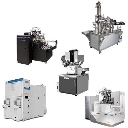
Types of Instruments
Technical Manufacturing Corporation offers numerous ultra-precision instruments that are capable of measuring particles at both the sub-nanometer and sub-angstrom scale. Some of these instruments include:
- Nanotech/Nanofab:
- SEM/TEM
- FI
B Milling
- E-beam Lithography
- STM
- Advanced Microscopy Centers:
- SEM/TEM
- AFM/SPM
- Confocal microscopy
- Multi-Photon Microscopy
- Single-Photon Microscopy
- Super-Resolution
- Semiconductor Manufacturing:
- Wafer Inspection
- CD-SEM
- Failure Analysis
- Defect Review/Repair
- Photonics:
- Petawatt Lasers
- Interferometry
- Virtual Reality
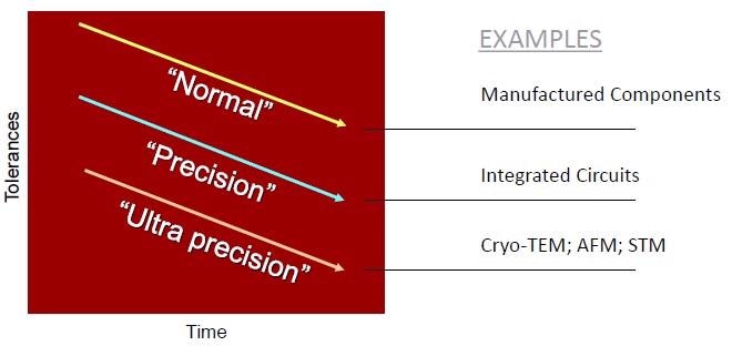
Trends in Discrete Part Manufacturing
As tolerances in nanoscale facilities continue to increase in their stringency, the resolution requirements are getting higher and higher. For example, while manufactured components remain at normal accepted tolerances, integrated circuits and techniques such as cyro-TEM, AFM and STM require now have tolerances that must be in the ultra precise range.

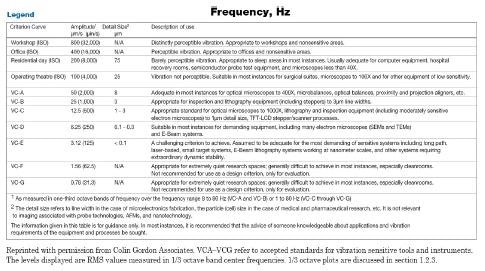
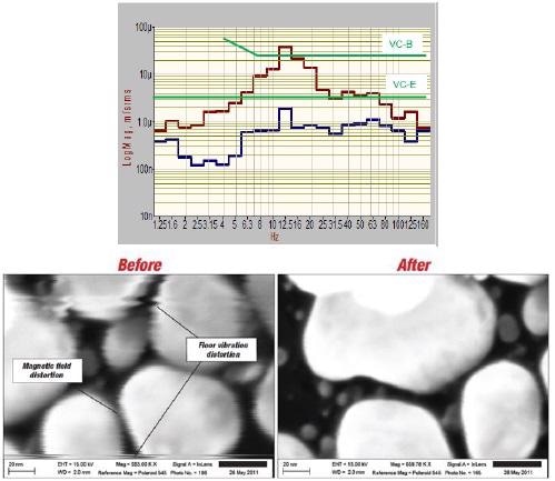
Floor Vibration Criteria – The VC Curves
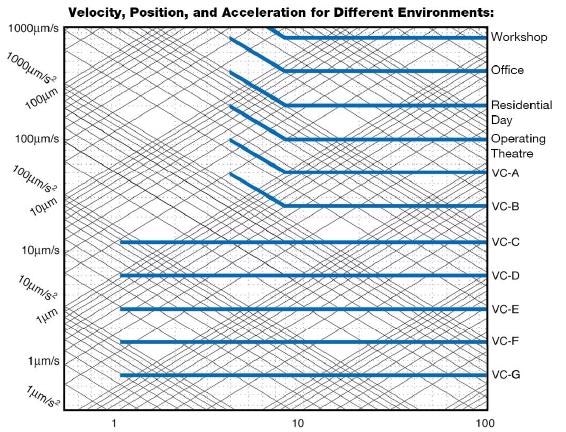
- Novel tool vibration criteria trends are becoming increasingly stringent in their requirements.
- Current developments have been focused on establishing the precise definitions for new and low amplitude generic criteria.
- VC-D was found to be the lowest out of all original VC curves; at the same time VC-M and below VC curves were also defined.
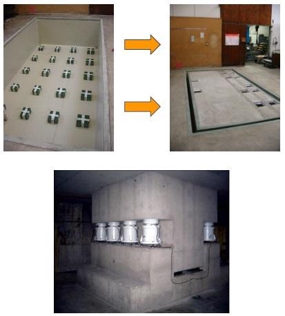
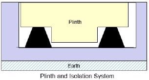
Traditional Approach: Isolated Concrete Plinths
Various types of concrete plinths can be used in this industry, of which include:
- Hard Spring Supported Plinths
- Mass-spring-damper
- High fn
- Amplifications that can reach as high as 1.4x fn
- Soft Spring Supported Plinths
- Plinths tend to isolate at lower frequencies
- Fn value often coincides with internal tool isolators
- Plinths that have been Decoupled from their Primary Building Foundation
- Not effective during substantial isolation
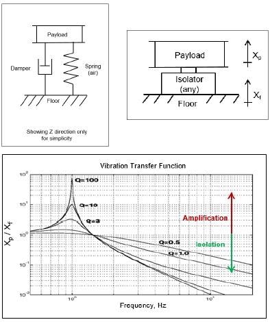
Passive Vibration Isolation
As a functioning mass-spring-damper, this isolation techniques passes low frequencies while simultaneously simplifying resonant frequencies and filtering high frequencies. Additional characteristics of this isolation method include:
- Resonant frequencies of approximately 2 Hz of self-leveling air isolators are independent from the payload mass.
- All axes exhibit 6 degrees-of-freedom
- Transfer function is provided rather than an absolute vibration level
- Payload vibration spectrum can be obtained through the use of a Multiply Vibration Transfer Function by floor noise spectrum
- Compromise exists between the amplification at resonance and isolation at high frequencies through the use of this technique
- Damping results in lower amplifications exist at resonance levels; however, a greater amount of energy is transferred when present at higher frequencies
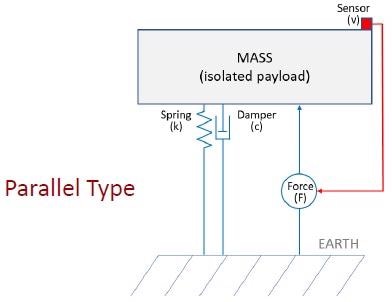
Parallel Active Vibration Isolation
- Capable of detecting payload vibrations, which initiates the corrective force to be applied to minimize the sensor output
- Typically used for stage motion cancellation as compared to floor vibration isolation applications
- Limited active bandwith
- Limited low frequency vibration cancellation
- Does not function well when stacked under instruments that have low frequency isolators installed within their structure
- Requires extensive tuning and re-tuning procedures
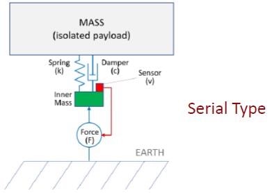
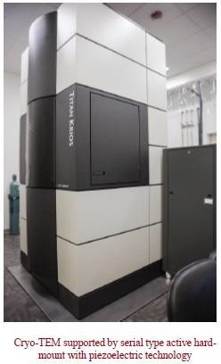
Serial Active Vibration Isolation
- Detects the vibration that is present above the “inner mass” of an object, which initiates a corrective displacement procedure to occur
- Passive spring filters payload resonances from sensor
- Exhibits a hard-mount design without any soft-air suspension incorporated into its structure
- Can be stacked under other instruments, as this instrument is specifically designed to isolate tools that exhibit a built-in isolation system
- Exhibit the widest bandwidth as compared to other isolation systems
- Considered to have the best low frequency isolation
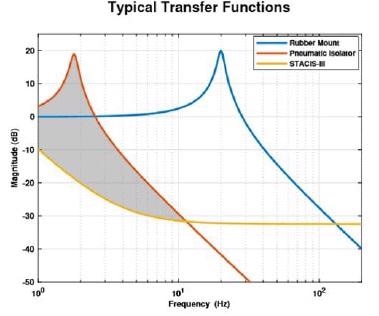
Vibration Isolation of Different Approaches
- Plinths located on rubber springs are assumed to have an fn value that is equivalent to 20 Hz, whereas plinths on air springs are assumed to have a fn value that is equivalent to 2 Hz.
- The difference between STACIS and air springs is 100-fold in regards to their performance rates at 2 Hz
- A critical approach that is used for microscopy techniques occurring within the 1-30 Hz range
- Acoustics control functions when isolation frequencies are above 20-30 Hz
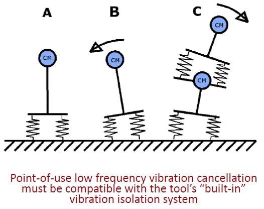
Planning Isolator Compatibility
Sensitive tools are typically equipped with low frequency air isolators, which can be both active or passive depending on the type of tool. As a result, these tools often require second stages of isolation that are up to 100 times greater in stiffness measurements to ensure the compatibility of these instruments. As a result, the point-of-use low frequency vibration cancellation procedures must be compatible with the internal vibration isolation system of the tool at hand.
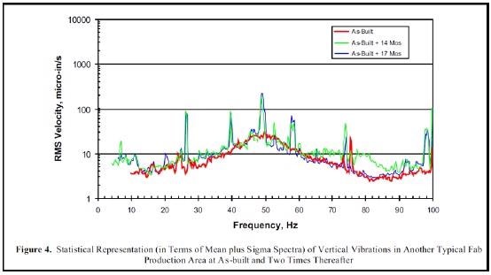
Planning According to Rising Vibration Levels
Vibration levels will normally increase over time as a result of the building being populated with various types of equipment and personnel, as well as due to the different activities that occur with any given building. As a result, vibration levels are expected to increase by as much as 15 dB, or greater, within the first 17 months.
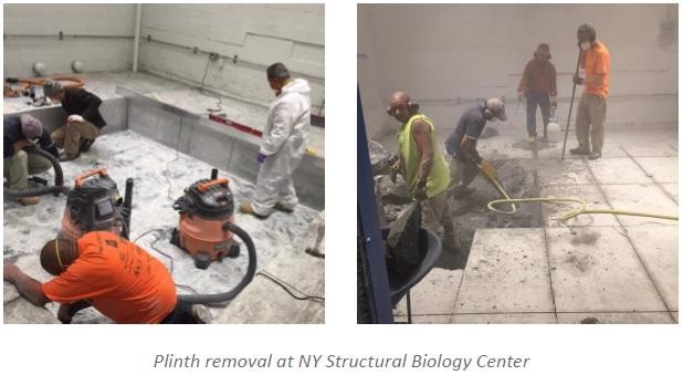
Planning Plinths
Plinths typically provide a limited low frequency vibration isolation. While plinths can amplify vibrations by up to ten times the critical frequency range, they may remain limited in their ability to meet required vibration criteria of particularly sensitive tools.
Unfortunately, as a result of this limitation, it may be required to remove plinths from these systems which is both an inconvenient and costly procedure to complete. In addition, the removal of plinths can also disrupt operations and neighboring tools, as well as limit personnel access to the floor.
The Reality of Designing Buildings to Quieter Specifications
When buildings are designed to meet quieter levels, they also require a significant increase in associated costs. Since the construction of vibration levels cannot occur directly below the foundation of the building, the construction of even the quietest levels may not be possible.
Point of Use Solutions
- As node size decreases, cleanroom cleanliness requirements also increase; however, this may not be a practical resolution in the long term.
- Mini environment SMIFs and FOUPs were fundamental changes that improved the cleanliness levels within these locations.
- By reducing the overall requirements, customers can potentially save on building costs by utilizing hard-mount point of use solutions for sensitive tools.
Conclusion
To establish an effective Quiet Island, it is imperative that inertial velocity sensors exhibit low frequencies. Additionally, piezo actuators must also be capable of supporting payload static weight at an extremely rapid reaction time.
While vibration control of buildings remains in the early stages of development, researchers are hopeful that these plans will continue to improve over the next few years. It is crucial that these research and development procedures complement the tool’s isolation system rather than attempting to fight them.

This information has been sourced, reviewed and adapted from materials provided by Technical Manufacturing Corporation Vibration Control.
For more information on this source, please visit Technical Manufacturing Corporation Vibration Control.