Sponsored by Nanosurf AGReviewed by Olivia FrostJan 25 2023
Magnetic force microscopy (MFM) is one of the modes of scanning probe microscopy (SPM). As the name implies, it is used to map magnetic characteristics.
MFM investigates the local magnetic fields at the nanoscale, producing images that contain information about the sample’s localized magnetic features, such as magnetic domains and wall mapping.
It is a qualitative, contrast-based approach that has been widely utilized to characterize magnetic storage mediums, superconductors, magnetic nanomaterials, and even biological systems.
How Does it Work?
MFM operates with dynamic force mode and phase contrast. A cantilever with a thin magnetic coating is driven towards its resonance frequency f0, where a 180° phase shift in the resonance frequency occurs. Resonance frequencies are typically in the tens to hundreds of kilohertz range.
MFM determines the phase of the oscillating cantilever as it passes over the sample at a certain height.
When the magnetic moments of the tip and sample are parallel, an attractive magnetic force gradient is formed. As a consequence, the resonance curve shifts to a lower frequency, and a phase shift at the excitation frequency decreases (Fig. 1).
A repulsive magnetic force gradient caused by the anti-parallel magnetic moments orientation causes the resonance curve to shift to a higher frequency, followed by an increase in phase shift at the excitation frequency. The cantilever reacts to out-of-plane fields.
As the tip is raised off the surface, the sample's magnetic forces acting on the cantilever are measured, distinguishing the long-range magnetic forces from the short-range atomic forces between the tip and sample.
The distance between the tip and sample is a key parameter to optimize for effective MFM operation. The resolution will be impaired if the tip is too far away from the sample. If the tip is too close to the sample, the topography will be tangled into the MFM signal, significantly complicating its analysis.
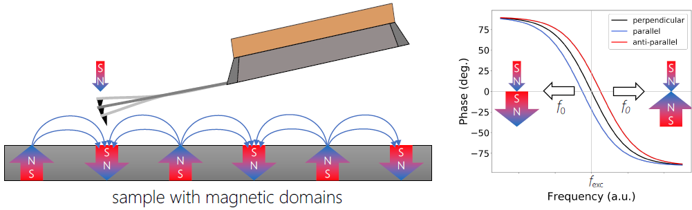
Figure 1. A schematic representation of MFM. If the local magnetic moments are parallel, i.e., magnetic field in the sample is aligned in the direction of the tip magnetization, there is an attractive force causing a negative phase shift (blue curve), in the anti-parallel orientation (red curve), the repulsive force causes positive phase shift from the excitation frequency fexc. There is no shift in case when the magnetic fields of tip and sample are perpendicular to each other. Image Credit: Nanosurf AG
The magnetic probe is the key to MFM, like with other SPM-based techniques. Commercially available silicon-based probes are coated with various magnetic thin layers (e.g., cobalt alloys). There are various types of MFM probes available, including high-moment, low-moment, and low-coercivity probes.
MFM can work in either a single or dual pass mode. The MFM tip passes over the sample at a fixed height in the single pass setting. To maintain a consistent gap, the slope between the sample and the scanner should be adjusted. This implementation of MFM is the quickest and has the least tip wear.
The tip-sample distance cannot be kept constant as the topography is not measured. To prevent topographical convolution in the higher parts, the lift height must be determined by the highest areas in the sample. This reduces resolution and contrast.
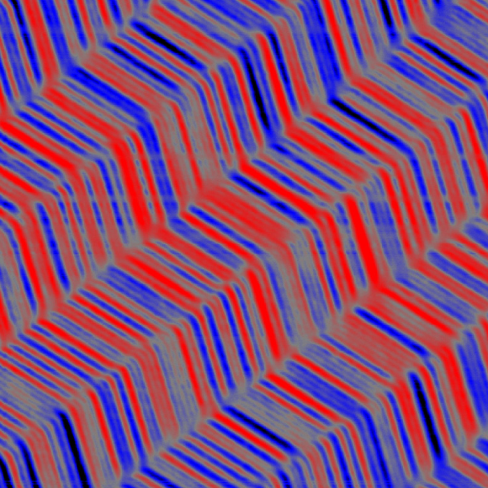
Figure 2. Magnetic force microscopy of digital backup tape with magnetically stored data. Scan size: 50 x 50 μm2. Image Credit: Nanosurf AG
The cantilever passes over every line twice in the image in the dual pass mode. The MFM tip captures topographical data in dynamic mode during the first pass. The tip is then elevated above the sample surface by an amount specified by the user for the second pass.
The tip follows the contours of the terrain in the second pass, keeping the tip-sample distance constant throughout each scan line. The amplitude of the second scan can be reduced to stay closer to the surface than in the first topography recording scan.
Optimization comprises a tradeoff between having the tip as close to the sample as possible while not being so close that it collides with it.
Applications of MFM
A. Magnetic Tape
One of the most common uses of MFM is the investigation of magnetic storage media, which include nanoscale characteristics that cannot be imaged using conventional methods. MFM is frequently utilized in this industry for quality control since it can detect defects and feature morphology required to maximize device performance.
The AFM image of a digital backup tape containing magnetically recorded data in Figure 2 is an example from the data storage industry.
The magnetized data domains inside this magnetic storage tape are readily visible in the 50 x 50 μm2 image. This simple example can be used to get acquainted with the MFM operating mode.
B. Hard Disk Drive
The most common application of MFM on magnetic storage systems is the hard disk drives measuring. In Figure 3, AFM and MFM are utilized to successfully evaluate a hard disk drive. Images of 2 x 2 µm2 are depicted below, with the topography image at the top and the MFM phase image at the bottom.
The dynamic force mode topography image displays diagonal grooves parallel to the recording tracks. However, the topography image does not reveal any magnetization information, which is visible in the equivalent MFM phase image.
In the MFM image, the red and blue areas indicate magnetic domains, with red depicting the repulsive forces and blue representing the attractive forces acting on the tip. A track distance of ~600 nm can be calculated using a bit length of ~70 nm, a length scale that can only be observed by scanning probe microscopy.
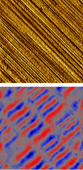
Figure 3. Magnetic force microscopy of hard drive with magnetically stored data. Scan size: 2 x 2 μm2. Image Credit: Nanosurf AG
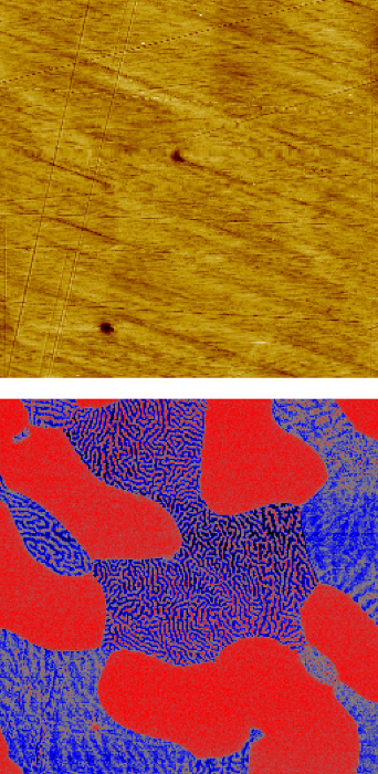
Figure 4. Magnetic force microscopy of a steel sample with 2 different magnetic phases. Scan size: 80 x 80 μm2. Image Credit: Nanosurf AG
C. MFM on Steel
Figure 4 depicts the use of a powerful MFM to observe magnetic domains in the materials science sector.
Polished stainless steel has a diverse morphology of various domains. An 80 x 80 µm2 topography image is presented, displaying some polishing scratches and a glimpse of some underlying morphology in the form of spherical dark domains.
The related MFM phase image, obtained using dual-pass MFM, provides a considerably more detailed view of the polished steel surface, exhibiting domains with low MFM contrast (red) as well as domains with a characteristic wormlike contrast scattered across the red domains.
The red domain is identified as the paramagnetic austenite phase that exhibits uniform contrast, while the wormlike domain is identified as the ferrite phase due to its ferromagnetic behavior.
The pattern and contrast of the wormlike domains are determined by the orientation of the magnetic field.
D. MFM of Thin Permalloy Films
The imaging of magnetic domains in thin ferromagnetic films is another stunning illustration of how useful the MFM is in observing magnetism in diverse materials. Permalloy (Fe0.2Ni0.8), in this example, is known for its extraordinarily high magnetic permeability.
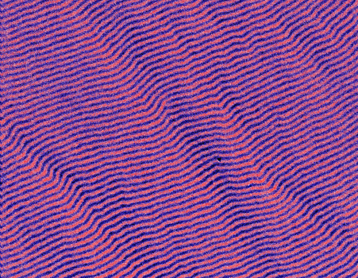
Figure 5. Magnetic force microscopy of thin permalloy film with stripe domains. Scan size: 30 x 30 μm2. Image Credit: Nanosurf AG
The residual magnetization of the film is visible in the 30 x 30 µm2 image of Figure 5, where the domains of opposing orientations form a pattern of stripes with a period of ~0.5 µm. The pattern period is determined by the magnetic characteristics of the film and increases with the square root of its thickness.
Conclusion
Magnetic force microscopy, a subset of atomic force microscopy, measures magnetic interactions between the tip and the sample to reconstruct the magnetic structure. Despite its origins as a qualitative approach, MFM has shown to be an outstanding characterization tool in both academic and industrial applications.
MFM has been extensively employed for magnetic nanostructures characterization and magnetic field distribution imaging. The key benefits of MFM are its high spatial resolution and sensitivity, capacity to operate in various environments, and the ability to examine magnetization processes using in situ magnetic fields.

This information has been sourced, reviewed and adapted from materials provided by Nanosurf AG.
For more information on this source, please visit Nanosurf AG.