The output of the Silicon Photonics industry needs grow significantly to keep up with Moore's Law and the ever increasing demand for photonics based components from wearables to optical computing chips. One of the obstacles is the current cost of aligning sub-micron structures during test and assembly. This is driven by the number of alignments neccesary and the lengthy time per alignment.
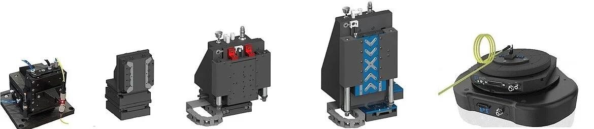
Image Credit: PI (Physik Instrumente) LP
The precision required poses several challenges for testing and packaging procedures, necessitating the precise alignment of fiber optic devices in high-throughput production settings.
100 times Faster
PI offers highly effective solutions for photonics alignment, seamlessly integrating and optimizing performance on the ACS motion controller platform. These solutions encompass high-precision, synchronized, multi-axis positioners coupled with PI's proprietary firmware-based alignment algorithms, leading to unparalleled levels of efficiency with reduction of alginment time of 99% and more compared to traditional methods.
Onboard Photonics Alignment Algorithms
Comprehensive User-Friendly Software Packages Enabling Easy Integration
The comprehensive package includes PI's MMI Application Studio, a robust and user-friendly tool for configuring, fine-tuning, programming, and characterizing motion performance.
The SPiiPlus Motion Simulator accelerates tool development through onboard routine programming at the controller level and interfacing at the host level, even before hardware delivery.
This accelerates time to market by leveraging ACS host application libraries for widely used platforms, including C/C++, COM, .NET, Python, MATLAB, Linux, and low-level socket communication.
PI also offers open-source graphical application examples in major programming languages like LabVIEW, Python, C#, and Visual Basic.

PI photonics alignment systems come with a variety of support tools for system setup and programming. Image Credit: PI (Physik Instrumente) LP
PI Proprietary Fast Alignment Algorithms for Quick Peak Finding
The fastest communication is the one that does not have to take place. Hence, PI embeds alignment algorithms within the motion controller rather than relying on an external host PC.
PI's onboard FMPA (Fast Multi-Channel Photonics Alignment) algorithms exhibit industry-leading performance, showcasing significantly higher throughput compared to traditional methods. Noteworthy tools in this array include:
- Archimedes Spiral Area Scanning
- SIN Wave Raster Area Scanning
- X-Scan Rounded Raster
- Gradient Search
- Fast Centroid Approximation
Labview drivers and example programs are provided with the alignment systems. Image Credit: PI (Physik Instrumente) LP
In silicon photonic circuits, precise measurement with high dynamic range and minimal electrical noise is pivotal.
For such applications, a high dynamic range optical power meter interfaces with a high-resolution analog output. This voltage signal is transmitted to the controller via a high-resolution analog input (24-bit), providing remarkably low noise and rapid synchronous data sampling up to 5 kHz.
Choice of Area Scan Algorithms: Circular and Raster
There are two available area scan algorithms for characterizing and determining the area with the primary optical peak. Both algorithms are optimized to minimize the excitation of mechanical resonances and ensure the shortest execution time.
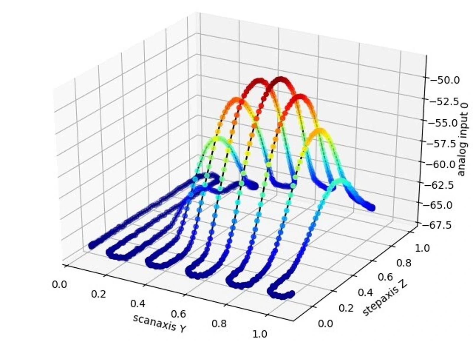
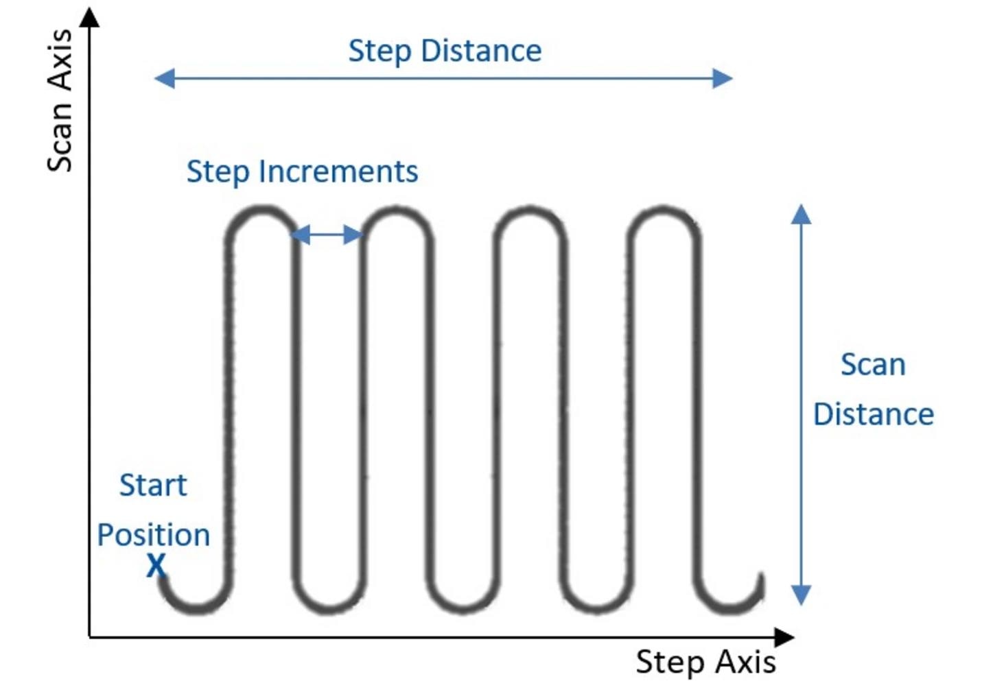
Modified SIN Wave Raster/SIN Wave Routine: The algorithm scans the user defined area continuously at a constant frequency. Scan axis, step axis, step increments, starting points on both scan and step axes, velocities on both axes, feedback channel, and signal voltage threshold can be defined by the user. Here, the high dynamic raster does not go through step type raster improving throughput and reducing impulse that leads to instability/delays in measurement. Image Credit: PI (Physik Instrumente) LP
Modified SIN Wave Raster/SIN Wave Routine: This algorithm continuously scans the user-defined area at a constant frequency. The user can define the scan axis, step axis, step increments, starting points on both scan and step axes, velocities on both axes, feedback channel, and signal voltage threshold.
In this case, the high dynamic raster avoids the step-type raster, improving throughput and reducing impulses that can lead to instability or delays in measurement.
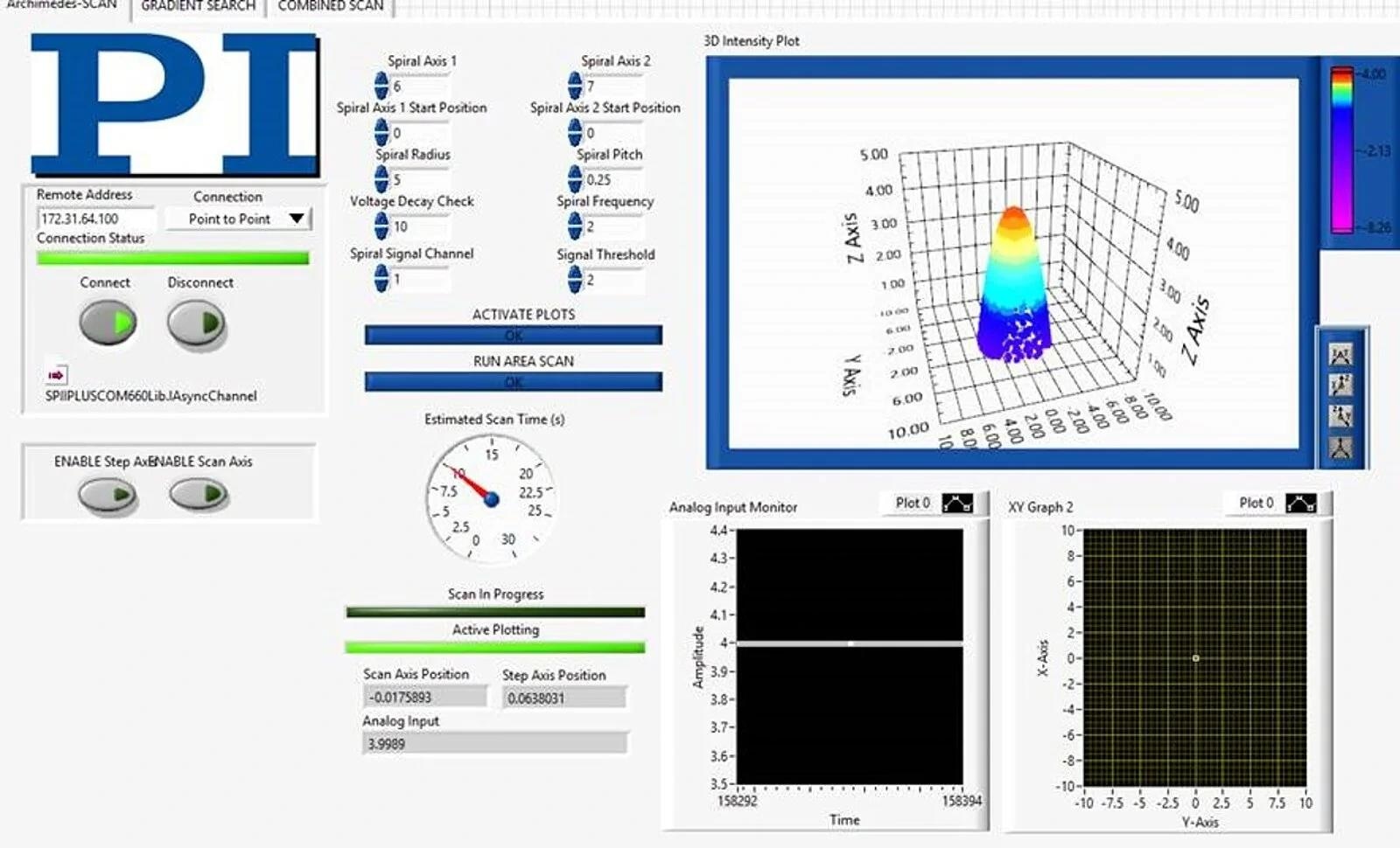
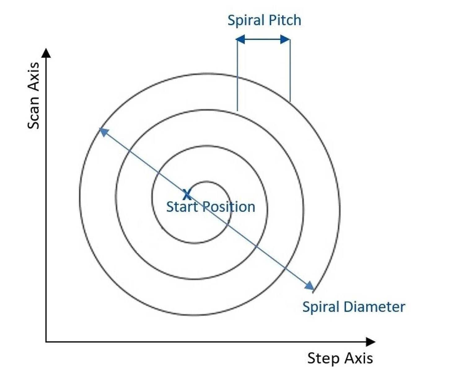
Spiral Routine: The algorithm scans the area in an Archimedes Spiral Motion in the XY plane. Here, the pathing is based on a pure frequency such that each turn of the spiral operates on a fixed inverse timing to user-defined spiral frequency. This pure frequency approach has two benefits: it avoids excitation of alignment system resonances and is self-compensating to deal appropriately with transitions of spiral radii that shift from large (mm) to very small (µm) without negative impacts of (short period) high impulses associated with non-pure frequency scanning. In this case, scan frequency, spiral diameter, spiral pitch, and signal threshold can be defined by the user. Image Credit: PI (Physik Instrumente) LP
Spiral Routine: This algorithm scans the area in an Archimedes Spiral Motion in the XY plane. The pathing is based on a pure frequency, ensuring that each turn of the spiral operates on a fixed inverse timing to the user-defined spiral frequency.
This pure frequency approach has two benefits: it avoids exciting alignment system resonances and is self-compensating to handle transitions of spiral radii from large (mm) to very small (µm) without the negative impacts of high impulses associated with non-pure frequency scanning.
In this case, the user can define scan frequency, spiral diameter, spiral pitch, and signal threshold.
Modified SIN Wave Raster/SIN Wave Routine. Image Credit: PI (Physik Instrumente) LP
Spiral Routine. Image Credit: PI (Physik Instrumente) LP
Gradient Search Algorithm
Gradient search algorithms are used in active optical alignment. A gradient search is a dither routine designed to detect the signal maximum by calculating and acting on the steepest gradient to the peak. The starting point of a gradient search can be the position determined by the area scan (where the first light was found).
It is especially important to run an area scan first when more than one peak is expected to avoid locking onto a spurious peak. Gradient calculations are done rapidly onboard to enable fast optimization and tracking of the peak signal.
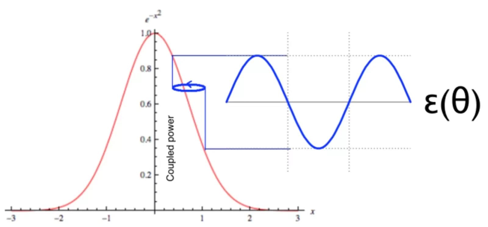
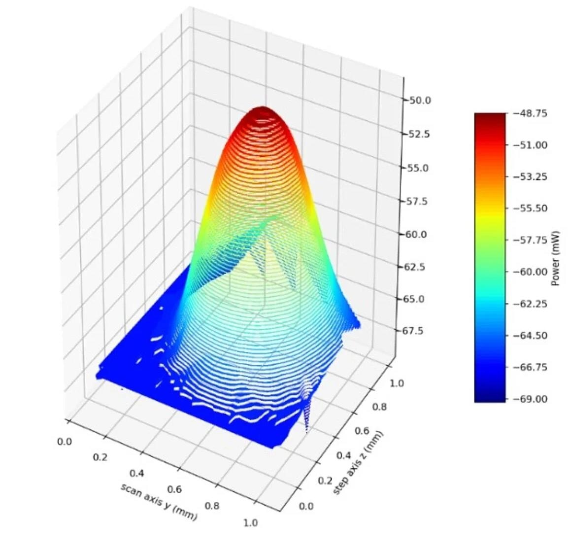
Graphical depiction of gradient determination via a circular dither, which modulates the coupled power (or other quantity) observed. The phase of the modulation with respect to the dither indicates the direction towards maximum while its amplitude falls to 0 at optimum. Image Credit: PI (Physik Instrumente) LP
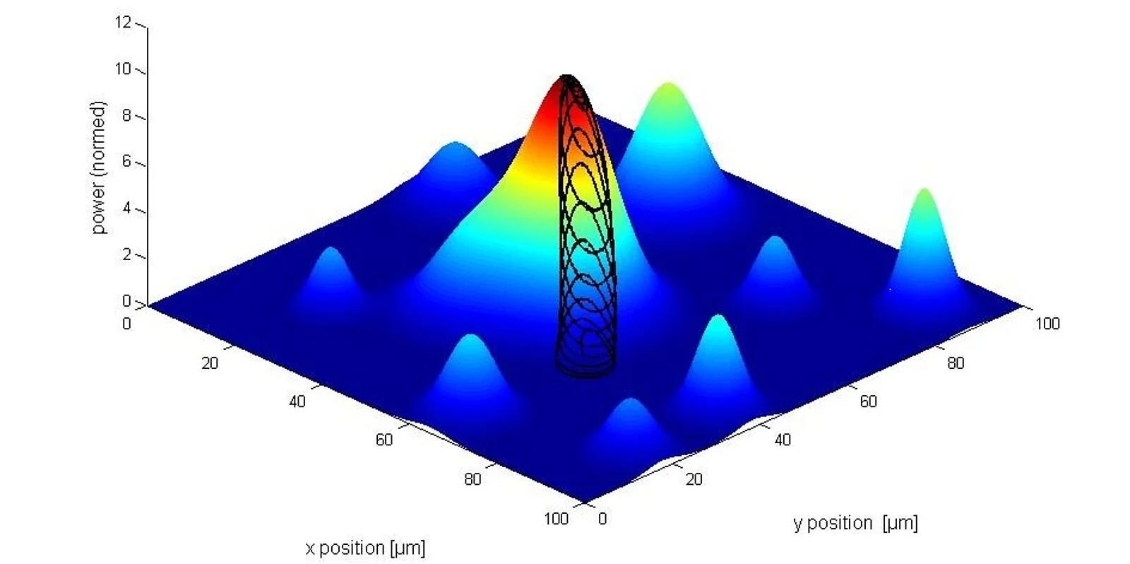
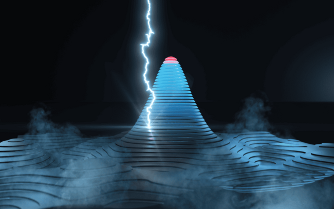
Optical power distribution and gradient search routine. Note the gradient search has to be started on the main peak, which can be determined by a raster scan or spiral scan. It will climb to the hill top, but has no way to find out if there are higher peaks around it. Image Credit: PI (Physik Instrumente) LP
PILighning First-Light-Capture Algorithm - Orders of Magnitude Faster
One of the biggest challenges in aligning sub-micron sized sized optical structures is the so-called first-light capture. First light is an optical signal above the noise level and is required a the starting piont of the gradient search algorithm. Especially in dual sided alignments, where finding first light can take minutes to an hour with traditional search algorithms, a new technology called PILightning can improve test and production efficiencies tremendeously. PILightning reduces the search for first-light by one or more orders of magnitude.
PILightning technology can reduce the first-light search time in dual-sided applications by more than two orders of magnitude. Image Credit: PI (Physik Instrumente) LP
Overview of Different Alignment Platforms
F-716, 6-DOF Parallel-Kinematics Air Bearing Motion System
The F-716 offers precise and high-performance motion across six axes. It is particularly suited for Fast Multi-Channel Photonics Alignment (FMPA), involving fiber arrays, silicon photonics circuits, and short-range metrology on wafers.
This system utilizes direct drive motor tech along with air bearings, ensuring a frictionless, contact-free design. Such attributes make it an excellent fit for dynamic applications running 24/7. Pairing this with high-resolution linear encoders enhances its suitability for alignment tasks.
The absence of mechanical bearings renders the F-716 maintenance-free, ensuring longevity ideal for cleanroom settings.
F-716 Low Profile Design
The F-716 air-bearing system boasts an incredibly low profile, standing at an overall height of just 100 mm. Its broad base and low profile enhance guidance performance, top-line dynamics, and servo-bandwidth (for high throughput). It is easily integrable, requiring minimal vertical space in setups/tools.
The low profile height of only 100 mm keeps the center of gravity low, improving stability and dynamics.
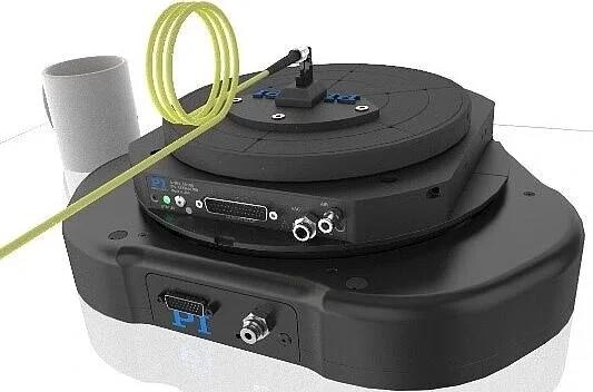
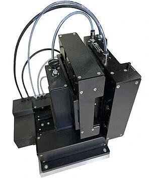
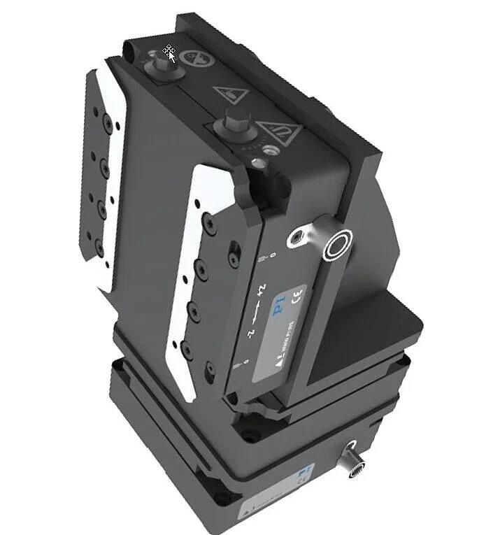
F-716 6-DOF Alignment System with fiber mount. Mug for size comparision. Image Credit: PI (Physik Instrumente) LP
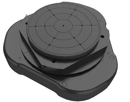
F-716 6-DOF Alignment System, tip view. Image Credit: PI (Physik Instrumente) LP
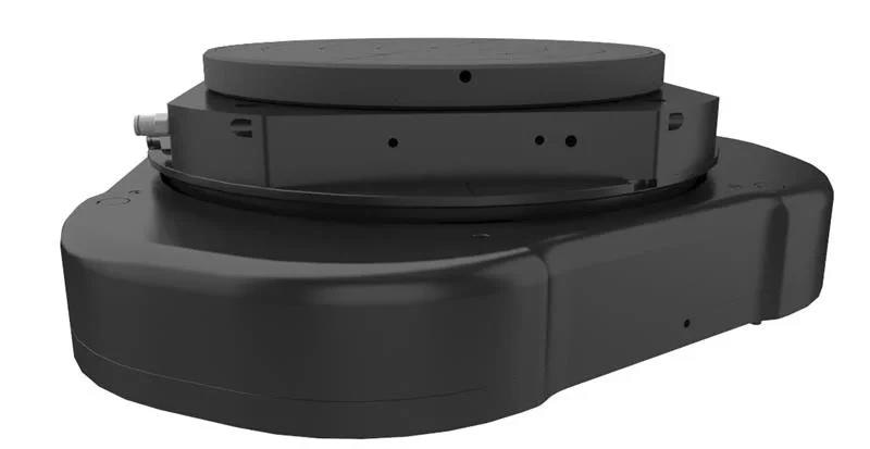
F-716 6-DOF Alignment System, side view. Image Credit: PI (Physik Instrumente) LP
F-716 Programmable Pivot Point
Utilizing Onboard Inverse and Forward Kinematics, this system provides automatic coordinate transformations, facilitating easy and precise adjustments around critical alignment points. This feature allows for quick angular modifications with high precision.
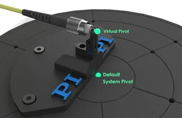
The default pivot point of the F-716 6-DOF alignment system is located on the surface in the center of the top plate. The controller can be programmed to move the pivot point to an arbitrary location, for example at the tip of a fiber, the waist of a beam, etc. Image Credit: PI (Physik Instrumente) LP
6-DOF Air Bearing Photonics Alignment System - Pivot Point Demo
6-DOF Air Bearing Photonics Alignment System - Pivot Point Demo. The video shows the multi-axis alignment stage pivoting around the tip of the ferrule. Video Credit: PI (Physik Instrumente) LP
The Compact F-142 Series High-Performance Air Bearing XYZ Stage
The F-142 XYZ air-bearing motion system offers high performance, dynamism, modularity, and compactness, serving as a versatile solution for Fast Multi-Channel Photonics Alignment.
It is configurable as XY, YZ, or XYZ, catering to various alignment needs such as Photonic Circuit surface coupling, fiber-to-fiber, and fiber-to-waveguide applications.
Its compact design makes it ideal for space-restricted applications, and the XYZ system includes a cost-effective counterbalanced Z version that minimally affects the stage's form factor.
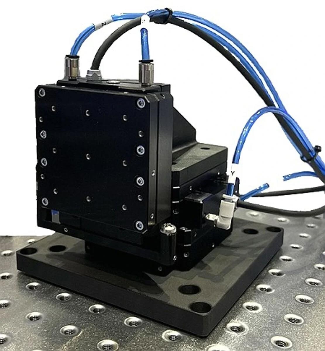
XYZ configuration of the F-142 for high-speed alignment. Image Credit: PI (Physik Instrumente) LP
Compact, 3-Axis Fast Photonics Aligner w/Air Bearings, Dynamic Long Travel Motion and Spiral Scan.
Compact, 3-Axis Fast Photonics Aligner w/Air Bearings, Dynamic Long Travel Motion and Spiral Scan. F-142 XYZ photonics alignment system showing off its dynamic capabilities with long travel, multi-axis moves, followed by a large area spiral scan and align routine. Video Credit: PI (Physik Instrumente) LP
High Frequency Scanning Motion with High Servo Bandwidth
The F-142 air bearing stage utilizes a voice coil motor and air bearings to achieve exceptional dynamics under lighter loads.
With a mere 250 g moving mass, the motor's force greatly enhances dynamic performance and throughput. Tests showcasing dynamic performance involve fixed-frequency rapid area scans at 20 Hz.
Analyzing reference versus feedback position, minimal phase lag and following errors are evident, allowing the stage to easily sustain 20Hz dynamically, handling 200 µm peak-to-peak repetitive alignment scanning motions effortlessly.
Thanks to its frictionless design, the F-142 averts wear and tear, necessitates no maintenance, and ensures a prolonged lifespan, making it ideal for 24/7 high-dynamic applications.
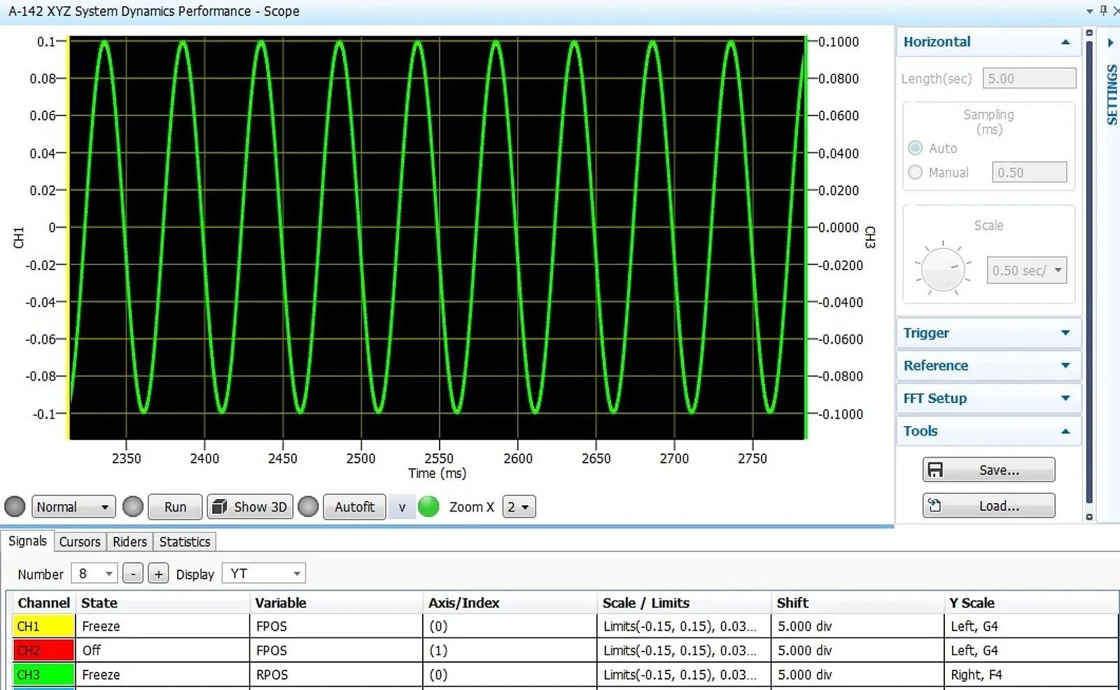
F-142, single axis scan performance, at 20 Hz, 200 µm peak-to-peak. Image Credit: PI (Physik Instrumente) LP
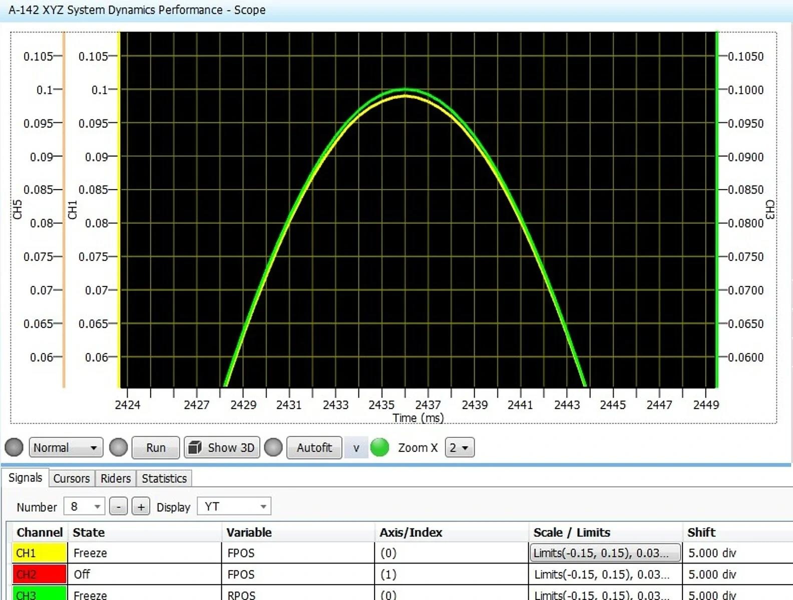
Here, the excellent dynamic behavior is seen between the target position (green) and the actual position (yellow) the deviation is on the order of 10 µm. Image Credit: PI (Physik Instrumente) LP
F-143 Series High-Performance Air Bearing XYZ Stage
The F-143 alignment system, a larger version of the F-142, boasts a 25 mm travel distance, 1 nm resolution absolute encoders, and higher force linear motors. It includes a pneumatic counterbalance on the vertical axis and an integrated brake.
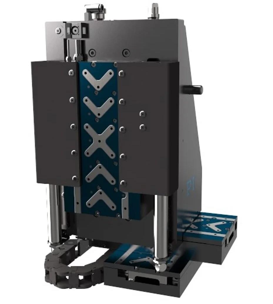
The F-143 multi-axis photonics alignment system was designed to significantly improve throughput in applications such as silicon photonics wafer test and validation. It provides 25 mm travel range, 1 nanometer resolution and together with its frictionless air bearings and high-performance alignment controller can reduce alignment time by 99%. Image Credit: PI (Physik Instrumente) LP
The F-143 multi-axis photonics alignment system aims to significantly enhance throughput, particularly in silicon photonics wafer test and validation applications. With its 25 mm travel range, 1 nanometer resolution, frictionless air bearings, and high-performance alignment controller, alignment time can be reduced by 99%.
Gantry Platforms for Large-Area Photonic Test and Assembly
Precise and high-throughput solutions are crucial for semiconductor or photonics tests and manufacturing involving densely packed nanoscale structures over large areas.
PI's flexible gantry systems, incorporating proprietary firmware-based alignment algorithms, have demonstrated a 100-fold increase in throughput compared to other methods, ensuring consistent and reliable outcomes.
PI's gantry systems employ two large, ironless linear motors to accommodate the demanding dynamics in photonics applications.
These efficient direct-drive motors, paired with two high-resolution linear encoders (offering nanometer or sub-nanometer resolutions) on the gantry axis, deliver highly repeatable positioning even during intense duty cycles.
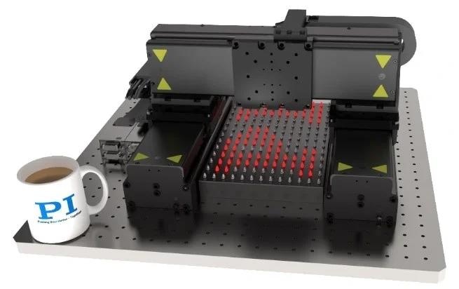
Miniature gantry for large area photonics test, based on three V-855 linear motor stages. ACS controllers are equipped with advanced gantry control algorithm that can handle two encoders on the gantry axis and control yaw. Image Credit: PI (Physik Instrumente) LP
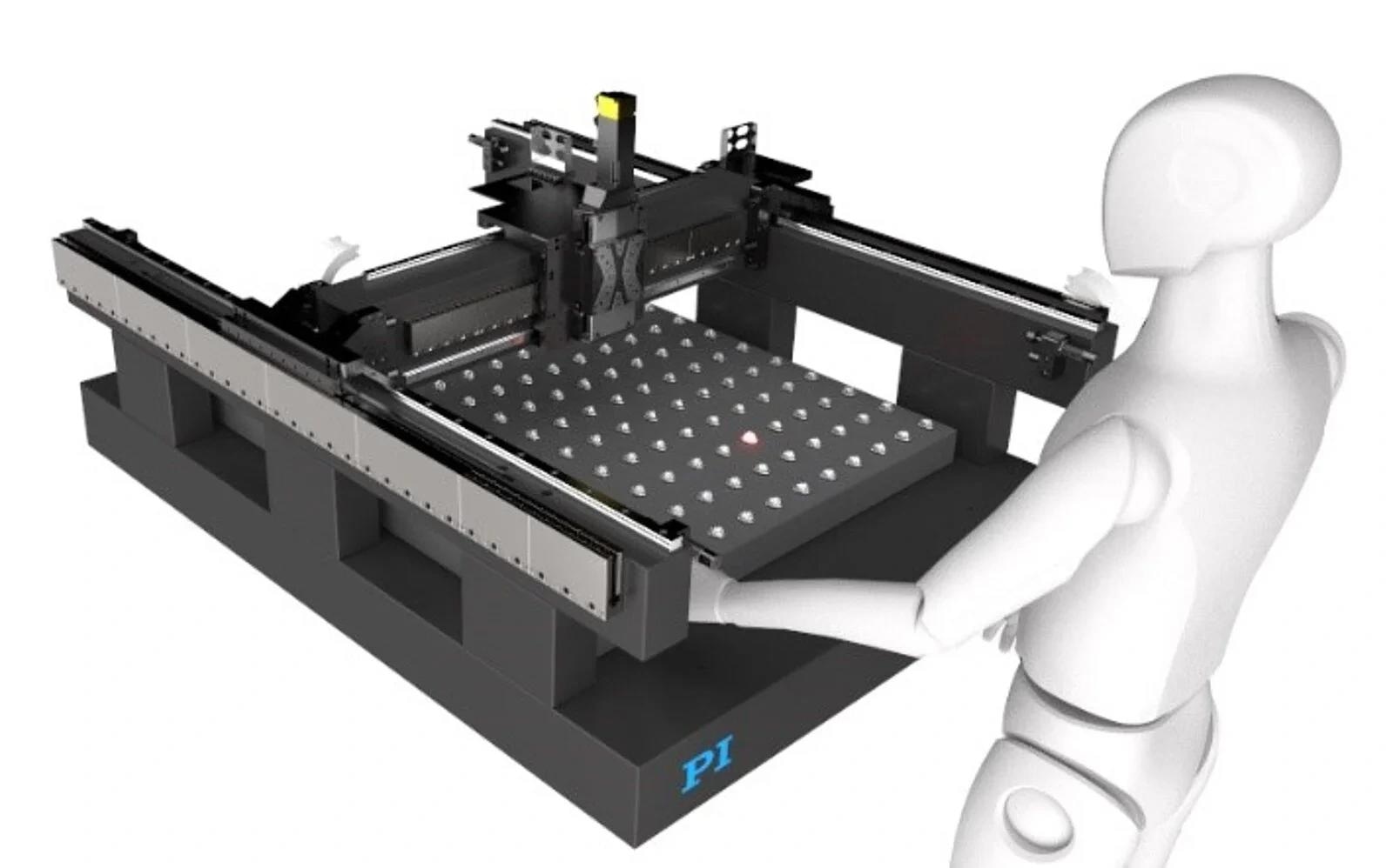
Granite-based large gantry system with algorithms for fast emitter array alignment. Image Credit: PI (Physik Instrumente) LP
XY Gantry Positioning System, Compact, for Automated Photonics Test & Assembly
Compact, High Performance XY Gantry Platform for Large-Area Automated Photonics Test & Assembly. Flexible, fast gantry platform for large area photonic test & assembly. In this demonstration, first light on one activated pixel on an LED marquee board is found by the scan routine and later characterized by a fine scan and gradient search. Video Credit: PI (Physik Instrumente) LP
Other Examples of Direct Drive Modular Systems Using Mechanical Bearings
F-308 Compact XYZ Direct Drive Photonics Alignment System
The F-308 operates as an ultra-small linear-motor-driven alignment setup, offering 7 mm travel capabilities with 1 nanometer precision. It is based on the V-308 nanopositioning linear stage and presents several essential specifications:
- Its design embodies a low-profile, low-moving-mass, high-dynamic direct drive stage
- Integration includes a user-adjustable magnetic counterbalance, catering to vertical applications (handling up to 1 kg of load)
- The system boasts a highly dynamic direct drive employing a voice coil motor
- A proprietary linear encoder, PIOne, ensures high resolution (1 nm)
- Equipped with precision anti-creep crossed roller bearings
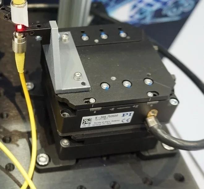
XY configuration of F-308 alignment system. Image Credit: PI (Physik Instrumente) LP
XYZ configuration of F-308 alignment system. Image Credit: PI (Physik Instrumente) LP
F-408 Compact XYZ Direct Drive Photonics Alignment System
F-408 is based on the V-408 linear motor stage, providing a travel range of up to 25 mm with 20 nm resolution. Notable specifications encompass:
- A compact, high-dynamic, low-profile, direct drive, modular design
- Integration of an efficient, compact, iron-core linear motor
- Utilization of PI's proprietary linear encoder (20 nm resolution)
- Employment of precision crossed roller bearings, designed for extended operational life at rated load
- An integrated pneumatic counterbalance with a brake for vertical applications
F-408, XY configuration with cable track. Image Credit: PI (Physik Instrumente) LP
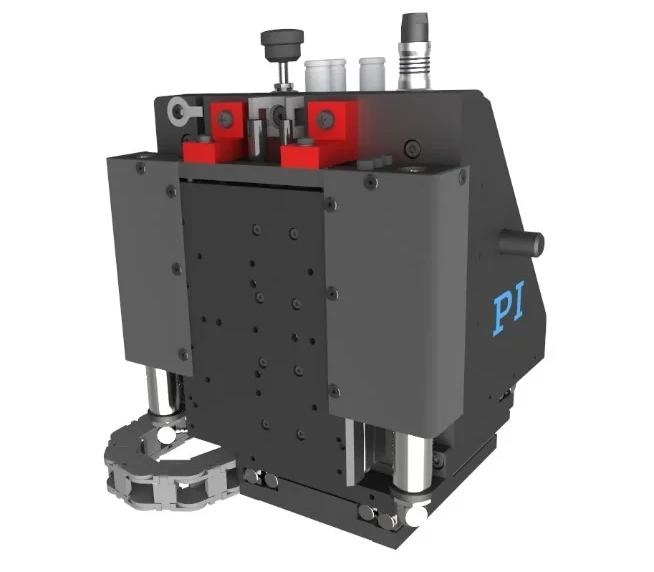
F-408, XYZ configuration with counterbalance for vertical axis. Image Credit: PI (Physik Instrumente) LP
F-508 Compact XYZ Direct Drive Photonics Alignment System
The F-508 is built on the V-508 linear-motor stage with crossed roller bearings. This stage offers extensive travel ranges of up to 170 mm and features an ultra-high-resolution PIOne incremental encoder. It has the following specifications:
- Exhibits a low-profile Al alloy body with minimal moving mass
- Functions with smooth dynamics through a compact, ironless linear motor
- Employs a high-precision PIOne linear encoder (2 µm pitch, 1 nm, interpolated resolution)
- Features precision anti-creep crossed roller bearings
- Includes an integrated pneumatic counterbalance with a brake tailored for vertical applications
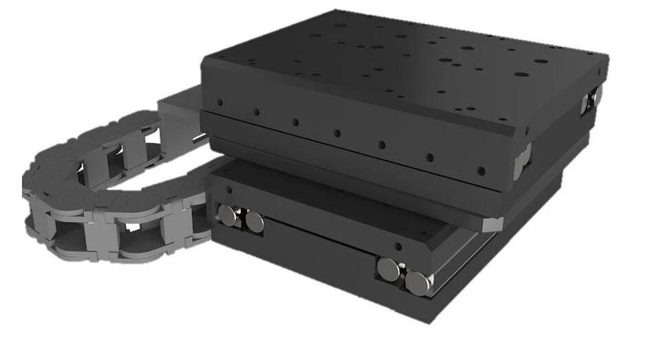
XY-Stage - Direct Drive Linear Stage w/Linear Motor, fast Scanning & Alignment, V-508 Linear Stage
XY-Stage - Direct Drive Linear Stage w/Linear Motor, fast Scanning & Alignment, V-508 Linear Stage. F-508 alignment system, XY configuration. Video Credit: PI (Physik Instrumente) LP
F-508, XYZ configuration with counterbalance for vertical axis. Image Credit: PI (Physik Instrumente) LP
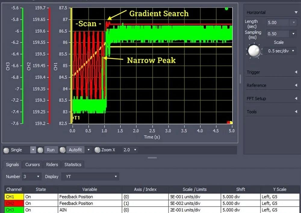
The above graphic shows a fast alignment run on a stacked V-508 XY stage with an ACS based motion controller and PI alignment routines. The scan range is ~0.3x1.5 mm, followed by an instantaneous gradient search. The complete alignment process takes about 1.2 seconds. The three signals shown are: X-Axis Position with vertical scale in mm (yellow); Y-Axis Position with vertical scale in mm (red); Analog Voltage from optical power meter (green). The power meter output range is ±10 V with +10 V representing max power and -10 V representing zero power. A narrow peak is found towards the end of the scan and the instantaneous gradient search starts right at the peak and maximizes the alignment within 0.2 seconds. Image Credit: PI (Physik Instrumente) LP
Alignment / Motion Controller based on ACS Control and Drive Modules
PI’s ACS based motion controllers come with a host of powerful algorithms and analysis tools. Image Credit: PI (Physik Instrumente) LP
The photonics alignment systems are fully assembled with a factory-optimized configuration under application-specific dummy loads.
System metrology for assessing repeatability and accuracy, including error mapping, is also undertaken. Information regarding system parameters, Error Maps, Alignment Algorithms, and safety parameters, is uploaded onto the high-performance A-81x series motion controller, which is an ACS-based controller.
The Motion System is prepped for turnkey operation upon delivery. ACS controls, known for their array of powerful tools and advanced capabilities, stand out as industry leaders, catering to high-demand applications for motion solutions.
Advanced Servo Control Tools
- ServoBoost, ServoBoostPlus
- Compensates Real-Time Disturbances for faster settling, better stability, lower jitter, better constant velocity, better following error
- Input Shaping
- Avoids exciting resonances
- PILOT
- Improves step-settle dynamic performance by reducing motor current requirements and heat generation (enhanced throughput)
- LearningBoost
- Increases motion system accuracy and throughput by learning and pre-emptively compensating for system disturbances
Expert Interview: Photonic Device Production Benefits from Air Bearing Technology
Expert Interview: Photonic Device Production Benefits from Air Bearing Technology. Why highly-dynamic air bearing alignment stages aid photonics innovation. Video Credit: PI (Physik Instrumente) LP
Modular Motion Control & Photonics Solutions from PI
PI, a leader in active photonics and optical alignment tech, introduces modular motion control solutions. The company pioneers ultra-swift mechanisms, controllers, and algorithms like Fast, Multi-Channel Photonics Alignment (FMPA) in various application areas.
The potential for frictionless air-bearing alignment has been acknowledged worldwide, proving vital in high-tech industries like semiconductor production, laser processing, and medical equipment manufacturing.
Active optical alignment brings benefits to applications such as silicon photonics, optical cable production, smartphone camera technology, metrology equipment, and beyond.
Effective Motion control plays a pivotal in most advanced technologies, such as Quantum Communications, Quantum Photonics and Computing, Nanosats, LIDAR, and optical logic. The increasing need for accelerated data processing, storage, and transmission benefits significatnly from the advancements in Silicon Photonics.

This information has been sourced, reviewed and adapted from materials provided by PI (Physik Instrumente) LP.
For more information on this source, please visit PI (Physik Instrumente) LP.