The portrayal of laser light in movies, often as a destructive force, contrasts its benefits in real-world applications.
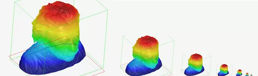
Image Credit: PI (Physik Instrumente) LP
In 1964, just four years after Theodore Maiman's pioneering laser operation at the Hughes Research Laboratory in California, the James Bond film Goldfinger hinted at laser cutting, albeit for less noble purposes.
Subsequently, powerful light sources resurfaced in cinema, with the Dark Side wielding light sabers and laser cannons against the Force of good.
Despite physicists predicting laser applications in the early 20th century, it was not until the 21st century that lasers became standard tools for material scientists and engineers. Applications ranged from cutting cellphone screens and dicing semiconductor wafers to enhancing the surface properties of metals.
Nonetheless, most laser applications focus on separating, melting, or removing materials. What if a laser could be employed to construct objects?
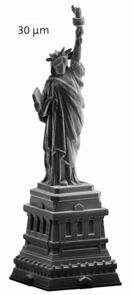
A miniature Statue of Liberty produced with laser lithography. Image Credit: NanoScribe
Enter Two-Photon Polymerization
The two-photon polymerization (TPP) process, also called laser lithography, transforms the concept of using laser beams for three-dimensional (3D) object creation from science fiction into reality. This technique is gaining rapid popularity, especially when intricate structures and small quantities are required.
TPP relies on two-photon absorption (TPA), a third-order nonlinear optical phenomenon whereby two photons are absorbed simultaneously, elevating a molecule to a higher energy state. This process selectively alters the material properties of a monomer gel.
Although TPA was initially described in the early 1930s, it took another three decades to prove the phenomenon with the invention of the laser.
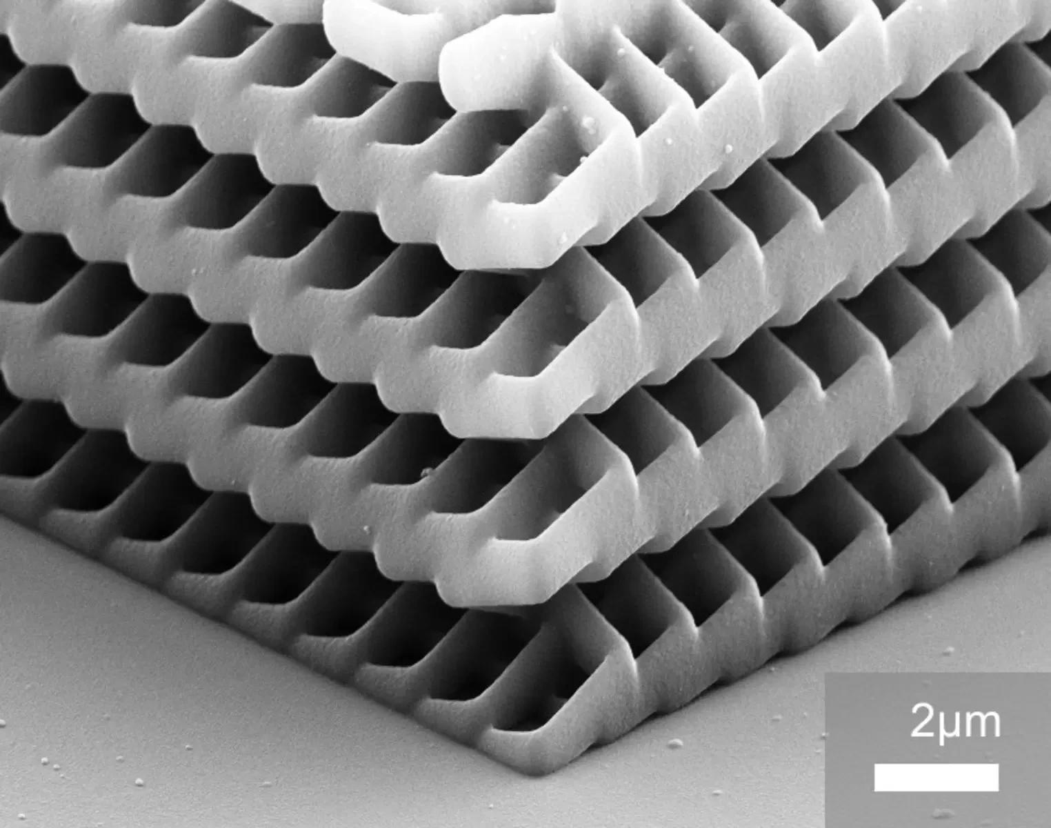
Photonic crystal produced with laser lithography. Image Credit: Nanoscribe
Today, TPA is frequently employed for micro-fabrication, utilizing highly focused coherent light through laser direct write methods to create sub-diffraction-limited structures. The advantage of TPA over one-photon absorption lies in its third-order process, which significantly reduces the absorption cross-section and enables the production of much smaller feature sizes.
Thanks to the high resolution of the TPP process, features as small as 100 nanometers, and sometimes even smaller, can be achieved. This capability facilitates the design of extremely lightweight yet robust structures and objects with high aspect ratios.
Laser lithography for micro-manufacturing systems has gained popularity lately because of the flexibility of the maskless 3D lithography method in crafting genuine 3D structures. There is a rising demand for this in photonics, micro-optics, biotechnology, and micro-mechanics.
In 3D-TPP micro-fabrication, a photo-curable resin gets exposed to a highly focused, 3D-scanned laser beam, forming polymerized voxels.
The TPP process happens with high spatial confinement at the focal point, preserving structures in the cured volume while easily removing adjacent volumetric spaces. This leaves a solid 3D object.
To achieve this, the laser beam can be directed by mirrors or by moving the resin on a multi-axis precision stage relative to a stationary beam. Sometimes, a mix of both methods is used. For both, the uniformity of resulting micro-structures relies on precise spatial positioning.
The nonlinear nature of the photo-polymerization process, as well as the slow scan speeds required for TPP, make controlling velocity with utmost precision crucial.
In a 3D process, coordinating motion among multiple nanopositioning stages or scanner axes becomes essential to deliver the required multi-axis trajectories.
Controlling Motion and Velocity in the Nanometer Range
This article explores controlling motion and velocity in the nanometer range. It delves into the performance of a compact, voice-coil-driven nanopositioning stage and software package that enables users to swiftly translate 3D data into multi-axis motion paths for TPP laser lithography.
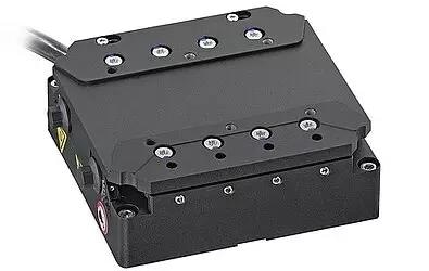
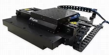
The V-308 nanopositioning stage uses a voice-coil linear motor and sub-nm resolution linear encoder for precise, closed-loop motion control. Image Credit: PI (Physik Instrumente) LP
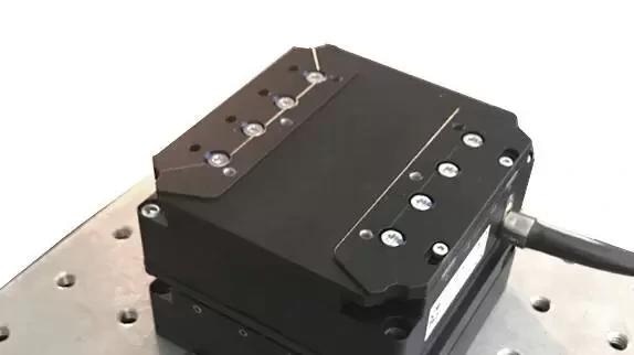
An XY-combination of the V-308 stage was mounted on a honeycomb breadboard for this test. Image Credit: PI (Physik Instrumente) LP
Given the stringent positional resolution requirements, the initial step involved assessing the steady position noise of the XY stage.
The stage was managed using an A-814 Series 4-Axis Motion Controller, utilizing ACS UDMnt Drives, and mounted on a three-point support system on a honeycomb TMC breadboard. This setup was placed in an office/lab environment on the first floor with a standard A/C and an adjacent roadway.
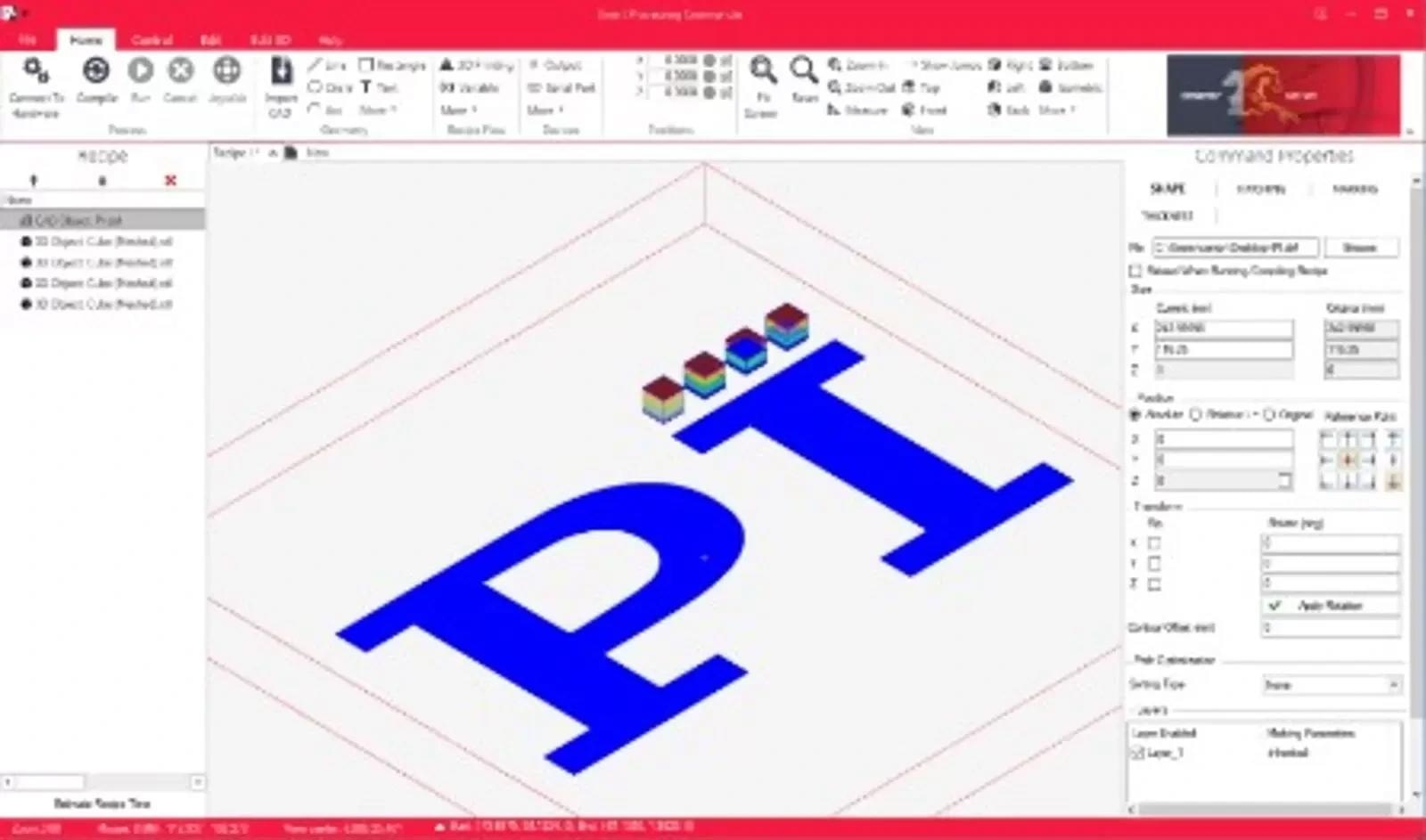
Smart Processing Commander (SPC) is a single-point laser system control software that works from industry-standard 2D and 3D CAD file formats. Shown here is a batch recipe setup using a DXF file of the PI Logo and a series of cube structures with alternating layer infills to fabricate woodpile-type structures. Image Credit: PI (Physik Instrumente) LP
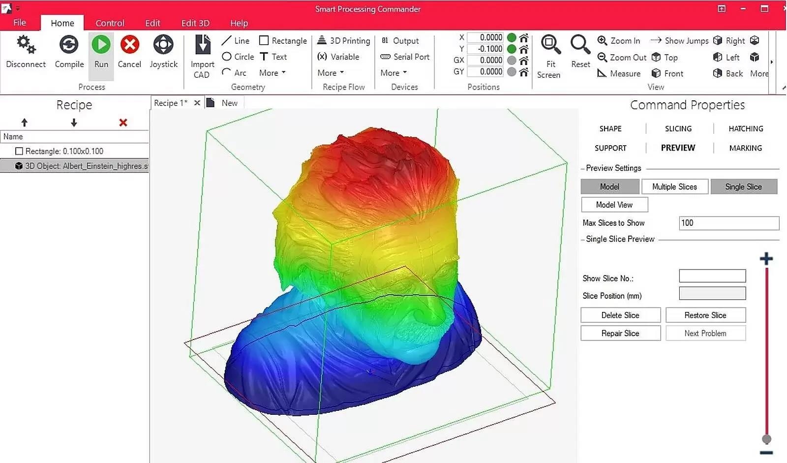
3D object in SPC; this advanced software package allows fast and efficient data import and process control. Image Credit: PI (Physik Instrumente) LP
Baseline in-position stability data were collected at 100 Hz over 5 seconds, utilizing integrated high-precision PIOne linear encoders on both axes (approximately 30 picometer resolution limit).
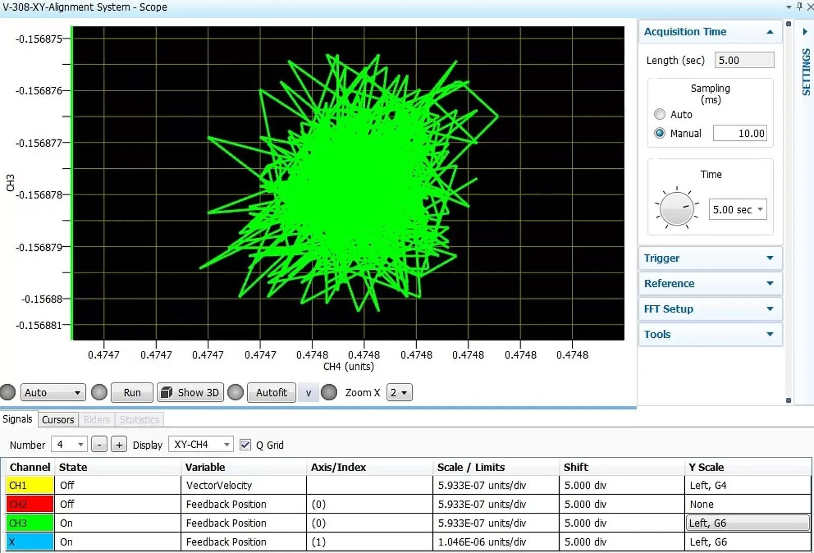
The graph shows the excellent XY-plane servo stability characteristics of the V-308 XY-stage, observed for 5 seconds. The radially symmetric position noise is on the order of only ±3 nm jitter. High servo stability with minimum positional noise is a prerequisite for highly constant velocity, especially for low-speed motion. Note: the axis units are millimeters, so the last digit indicates nanometers. Image Credit: PI (Physik Instrumente) LP
Dynamic Performance, Velocity Stability, and Position Error on XY Coordinated Motion for TPP Processes
A. 5 µm Rectangular Polymerization Process Path
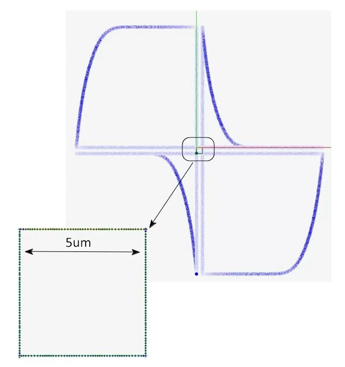
The advanced motion path planning feature allows for excellent velocity control in the areas of interest. The constant combined vector velocity is 100 µm/sec. The center green rectangle has a side length of 5 µm. Blue is motion path trajectory. The stages are tuned for TPP smooth scanning performance, and the coordinated digital trigger is used to shutter the laser. Image Credit: PI (Physik Instrumente) LP
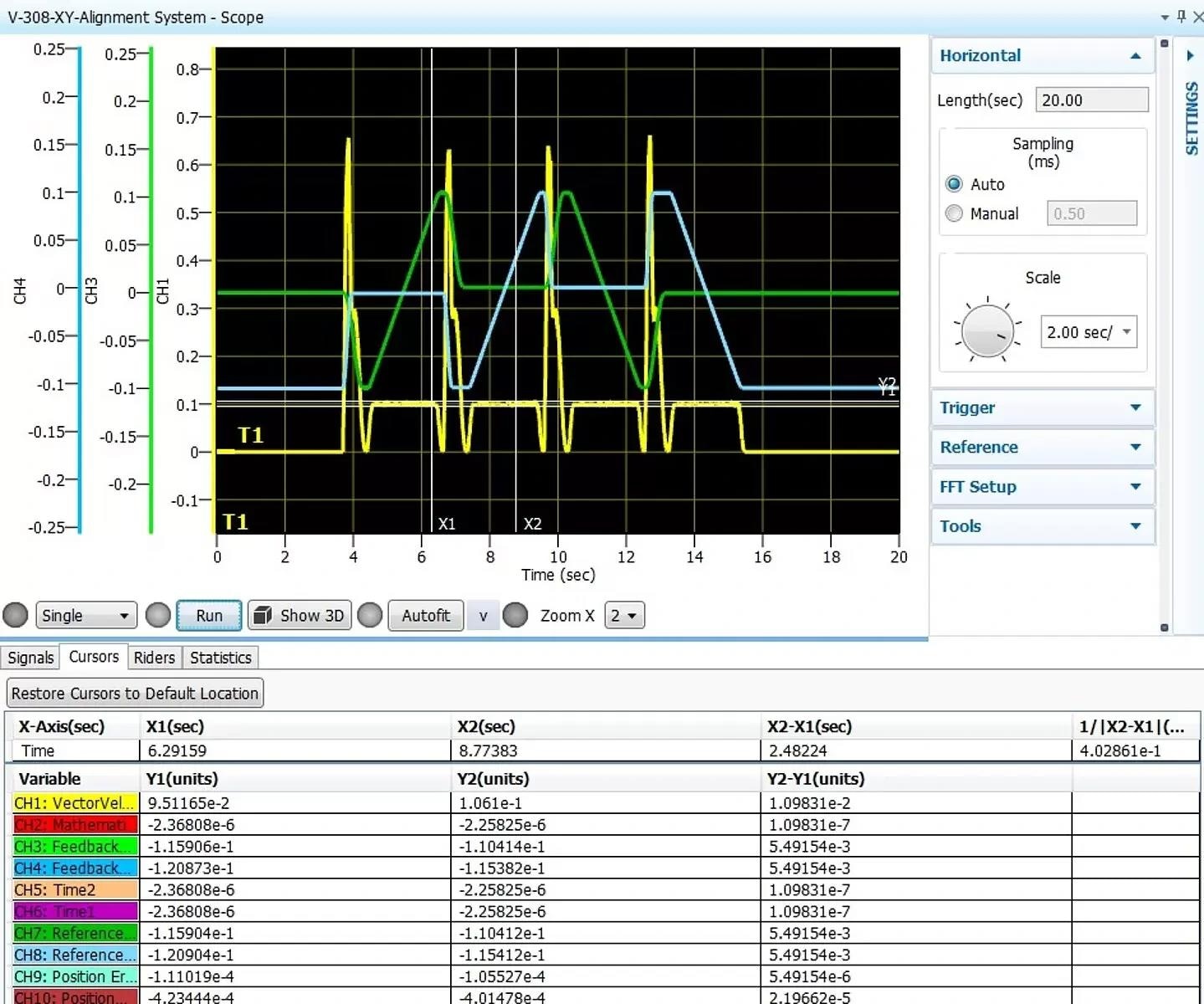
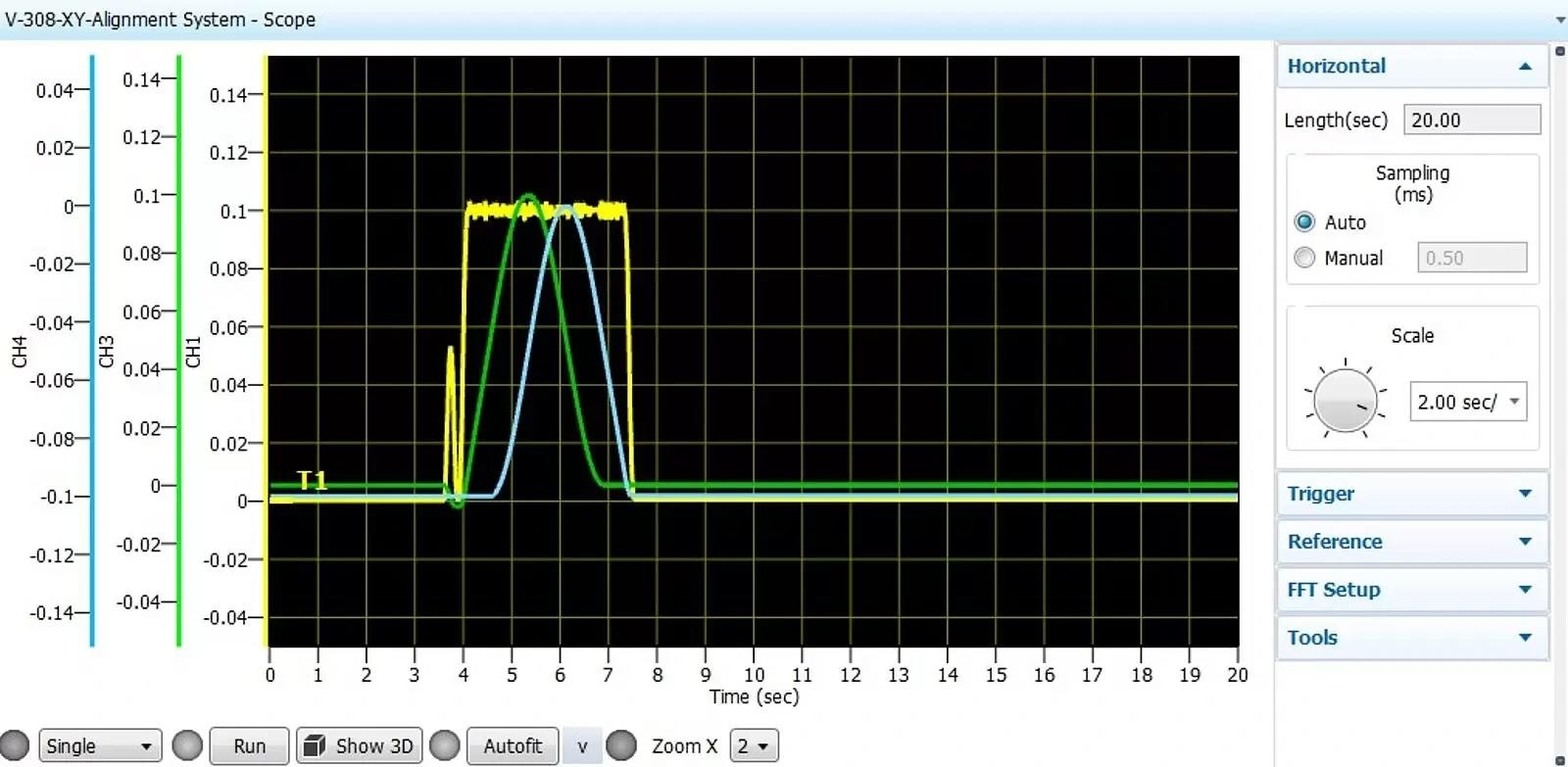
Motion Profile and General Performance Characteristics: On each side of the rectangle, the combined vector velocity has been coordinated by the controller to be constant at 100 µm/sec. In advanced path planning, the stages use lead-ins to accelerate and then maintain constant velocity with laser-coordinated laser shutter on corners. There are multiple features available for optimized path planning. Observed at left is X-Axis position in time (blue signal) and Y-axis position in time (green signal). Image Credit: PI (Physik Instrumente) LP
Zoomed view: Ultra-slow speed rate variation: The view above shows coordinated constant velocity performance with target velocity of 100 µm/sec (yellow) and a rate variation observed at ±5%. Image Credit: PI (Physik Instrumente) LP
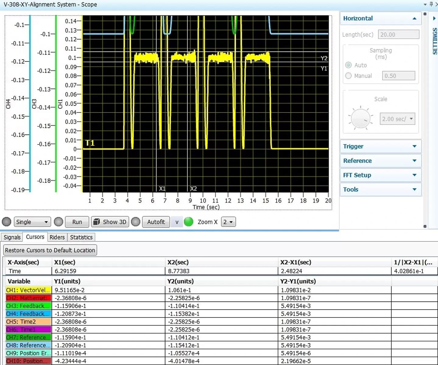
Position error measured during active motion on the X-axis is observed at ~±35 nm. Image Credit: PI (Physik Instrumente) LP
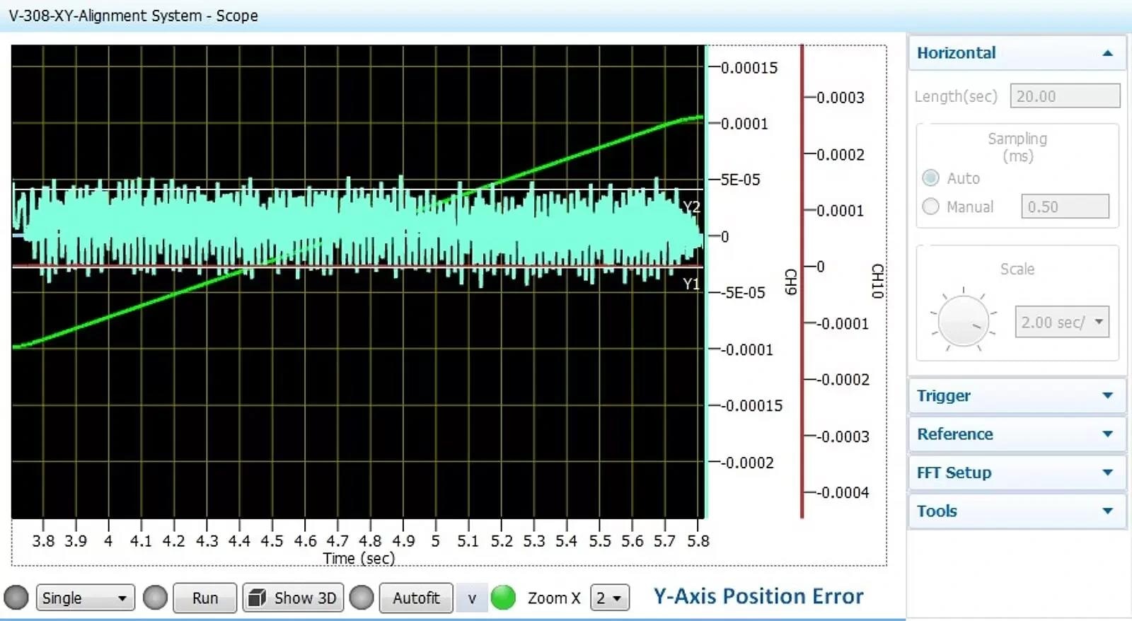
Position error measured during active motion on the Y-axis is observed at ~±35 nm. Image Credit: PI (Physik Instrumente) LP
B. 20 µm Rectangular Polymerization Process Path
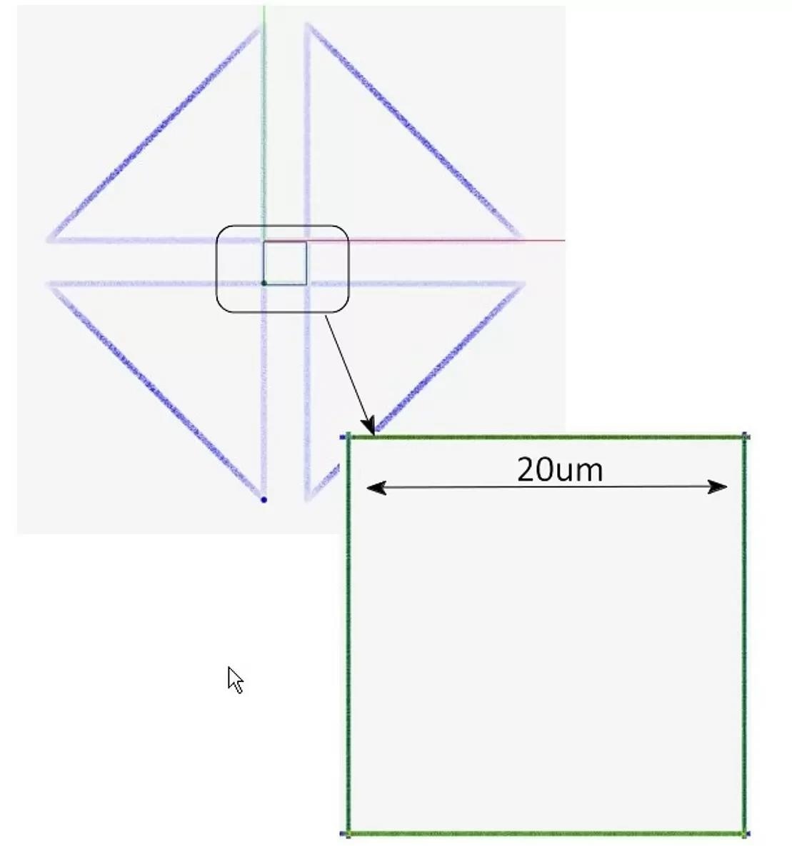
Here, a 20 µm square with advanced motion path planning is shown. The constant combined vector velocity is 100 µm/sec. Blue is motion path trajectory. The stages are tuned for TPP smooth scanning performance. A coordinated digital trigger is used to shutter the laser. Image Credit: PI (Physik Instrumente) LP
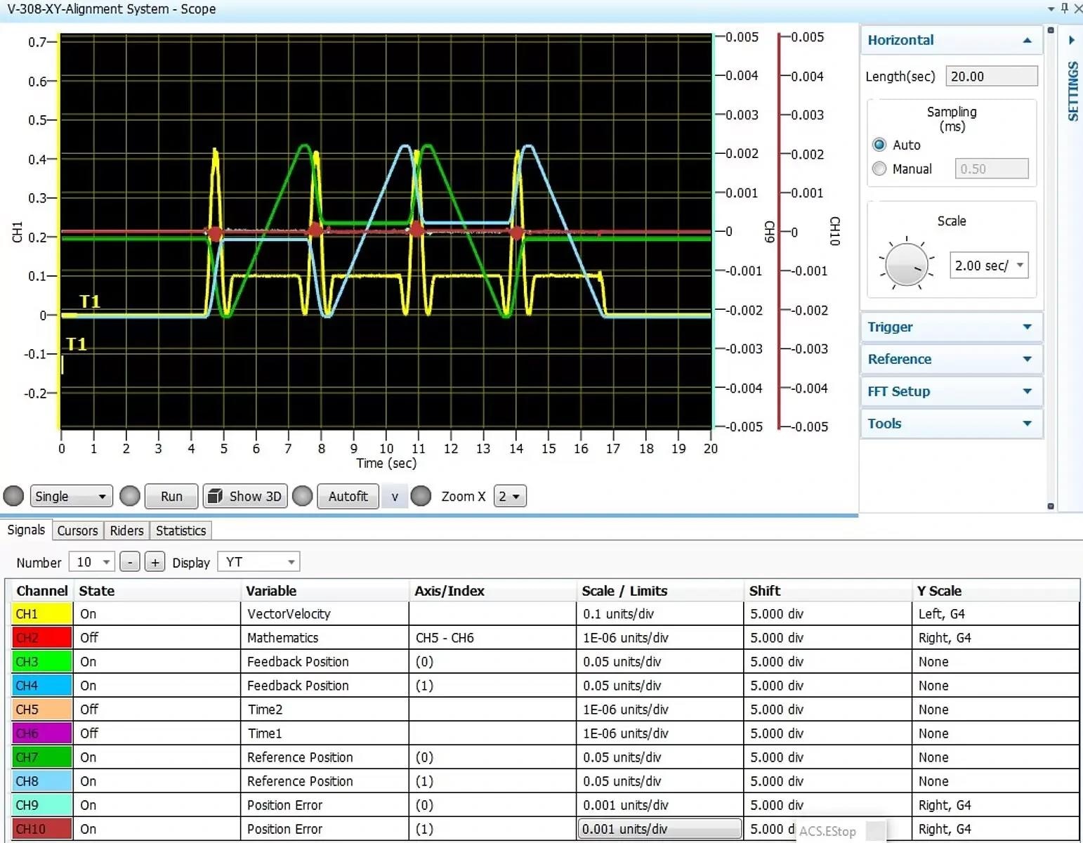
In non-active laser processed areas, the velocity moves to shorten process time and in processed areas is tightly regulated. On each side of the rectangle, the combined vector velocity has been coordinated by the controller to be constant at 100 µm/sec. In advanced path planning, the stages use lead-ins to accelerate and then maintain constant velocity with laser-coordinated laser shutter on corners. There are multiple features available for optimized path planning. Observed at left is X-Axis position in time (blue signal) and Y-Axis position in time (green signal). Image Credit: PI (Physik Instrumente) LP
Like the 5 µm rectangle, there was a position error of about ~±35 nm noted for both the X and Y axes. The velocity rate fluctuated around ~100 µm/s, with a margin of ±4 %.
C. 100 µm Rectangular Polymerization Process Path and Curvilinear Coordinated Polymerization Process Path
Finally, tests with a 100 µm rectangle and a curvilinear path were conducted.
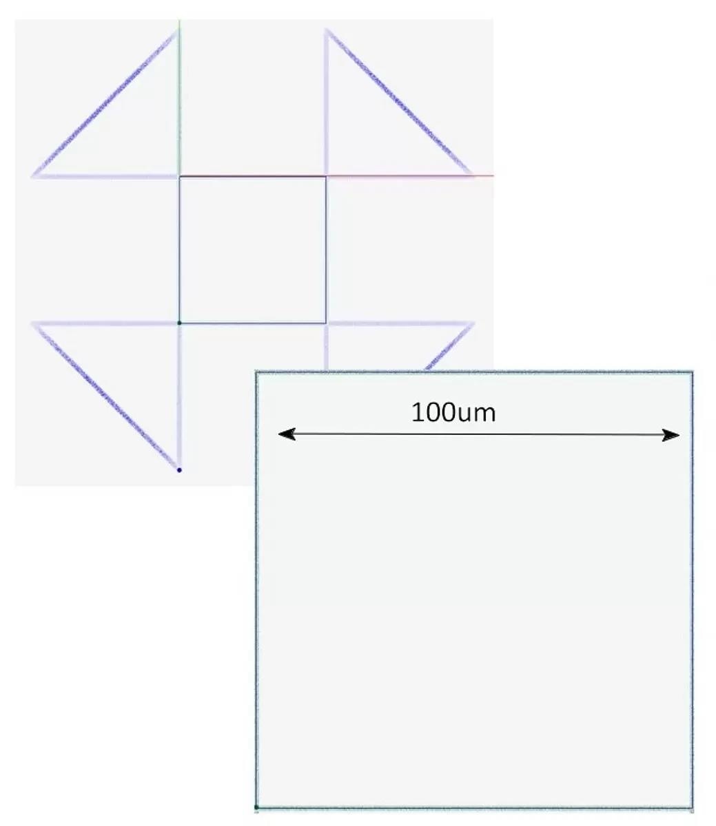
In the 100 µm rectangle, the observed performances were consistent with previous runs: ~±35 nm, positioning error, and 100 µm/sec ±5 % rate variation. Image Credit: PI (Physik Instrumente) LP
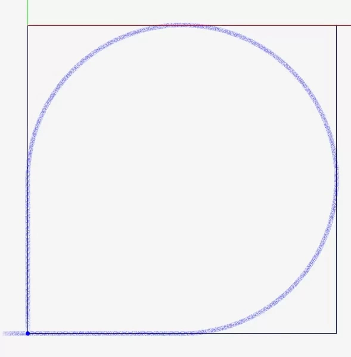
The graph shows a curvilinear path inscribed in a 100 µm rectangle, again with a constant combined vector velocity of 100 µm/sec. Blue is motion path trajectory. Image Credit: PI (Physik Instrumente) LP
The combined vector velocity of the curvilinear run has been coordinated by the controller to be constant at 100 µm/sec (yellow) with a rate variation of ~±3.5 % (100 nm/div). In active laser-processed areas, the velocity moves in a coordinated vector velocity-regulated fashion in XY. Observed at left is X-Axis position in time (blue signal) and Y-Axis position in time (green signal). Image Credit: PI (Physik Instrumente) LP
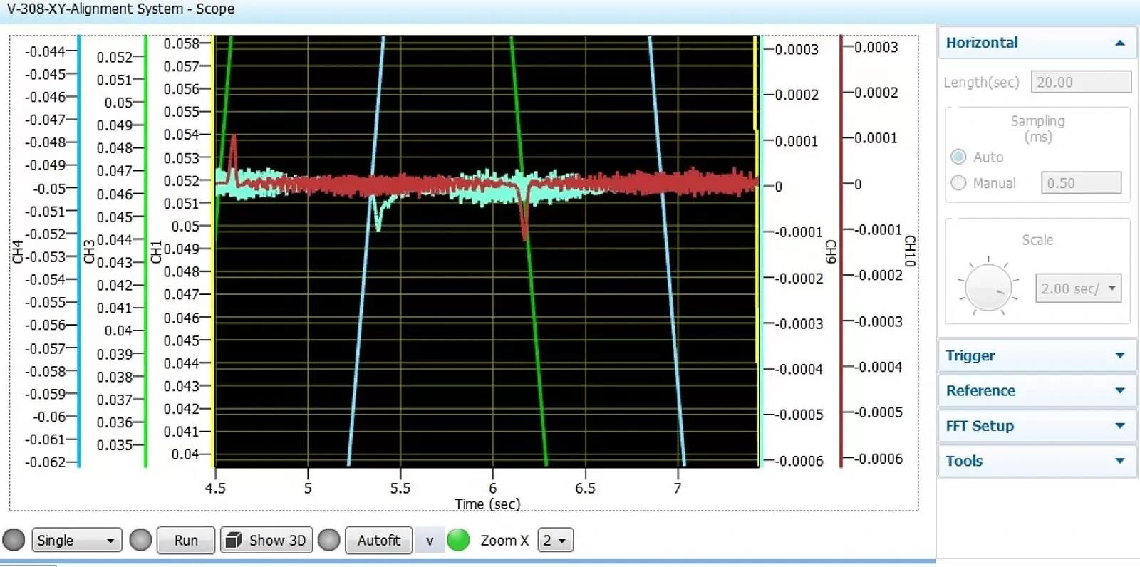
Error characteristics shown above (100 nm/div). The error is observed at ~±35 nm for the X-axis and ~±25 nm for the Y-axis. Image Credit: PI (Physik Instrumente) LP
Summary – Synchronized Low-Speed Performance of Voice-Coil Nanopositioning Scanners for TPP
This test aimed to confirm the ability of the V-308 voice-coil-driven linear stage to maintain the very low and consistent speeds essential for high-quality outcomes in TPP. The findings displayed excellent motion consistency, sustaining constant vector velocity along all tested paths.
During active scanning, minor position errors were noticed, measuring below 100 nanometer levels. These errors exceed the requirements for successful TPP outcomes despite less-than-ideal operating conditions and stage mounting surfaces. The absence of a lapped granite interface at the time of the test limited achievable performance.
The high motion performance partly stemmed from using the PIOne encoder technology, offering sub-nanometer interpolated resolution. If desired, further enhancements are also possible.
- PI's PILOT algorithm has proven effective in improving performance in alternate critical nanopositioning applications.
- Employing NanoPWM drivers can minimize noise.
- Mounting the stages on a lapped granite interface, as mentioned earlier, will positively impact precision.
Overall, the tests affirm that the V-308 voice-coil-driven XY-table combination provides an efficient, cost-effective solution for short-range TPP.
For Higher Precision and Longer Travel Requirements
Planar air-bearing XY-tables offer superior performance in motion smoothness, velocity consistency, straightness, flatness, and yaw control. An example is the compact A-311 XY-table depicted below.
Air-bearing XY tables, such as the A-311 compact stage, provide extremely constant motion, straightness, and flatness – ideal prerequisites for two-photon polymerization. Image Credit: PI (Physik Instrumente) LP
Integrated Flexure Guide Piezo XY and XYZ Tables
For travel ranges below 1 mm, piezoelectric XY and XYZ flexure tables are available. These provide ultra-precision nanopositioning in the single-digit nanometer range.
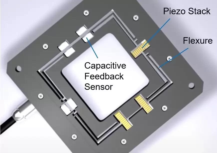
Basic design of a piezo flexure scanning XY-table. These 2-axis and 3-axis nanopositioning tables are the gold standard for accuracy, resolution, smoothness, and speed, when travel ranges in the sub 1mm range are sufficient. Image Credit: PI (Physik Instrumente) LP
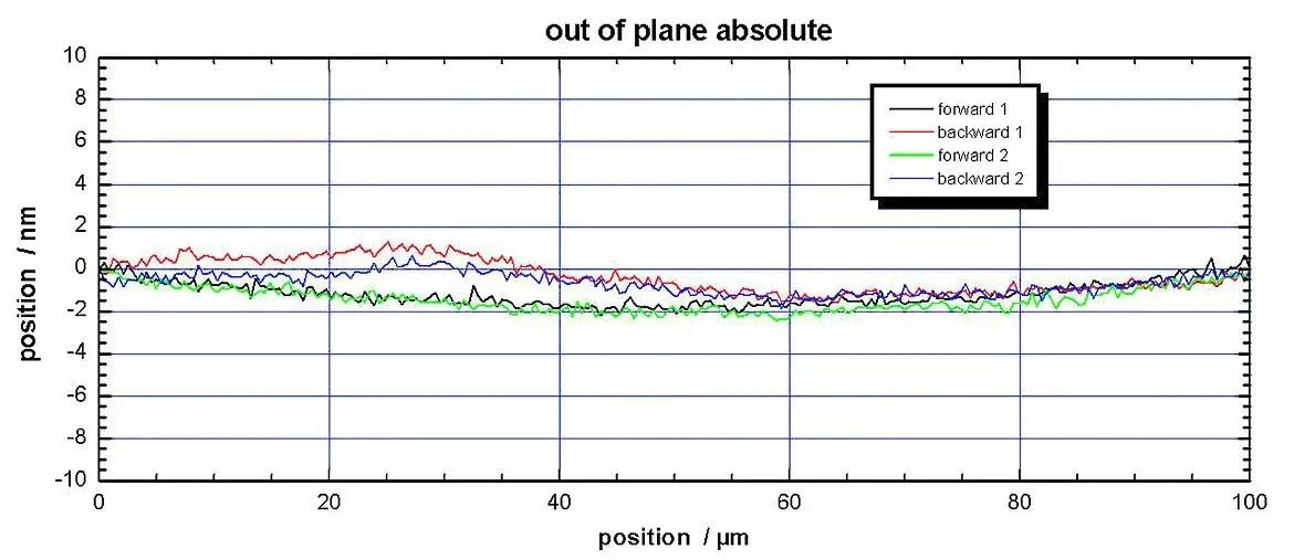
+/- 2 nanometer out-of-plane motion of the P-734 flexure-guided, planar nanopositioning XY table. Image Credit: PI (Physik Instrumente) LP
A highly compact piezo nanopositioning XYZ stage, the P-611.3SF model (featuring 100 x 100 x 100 µm travel and 0.2 nm resolution), has been utilized in TPP for the Fabrication of Complex-Shaped Particles and Structures in research conducted at the University of Colorado.

This information has been sourced, reviewed, and adapted from materials provided by PI (Physik Instrumente) LP.
For more information on this source, please visit PI (Physik Instrumente) LP.