Thanks to a new generation of ultra-short lasers, laser drilling is becoming the top method for forming small holes in various materials. These advancements enable cold ablation to produce reproducible holes that require minimal post-processing.
This strategy is gaining traction across a broad range of applications, such as aerospace component cooling, fuel injection nozzles, and inkjet printer heads, as well as creating microvias in printed circuit boards (PCBs).
There are various laser drilling techniques, with the most basic strategy involving the use of a single laser pulse to form a hole. Alternatively, the laser can be pulsed several times to eliminate successive material layers. In both cases, the size of the hole directly correlates with the size of the laser spot.
Additional common methods include trepanning and helical drilling. In trepanning, the laser beam is moved around the center point of the hole being drilled, allowing the hole size to be larger than the laser spot size. Helical drilling adds vertical motion to better control the hole’s side-wall quality. The latter two techniques require precise motion control to generate high-quality holes with the intended shape.
A broad range of motion technologies are available for laser materials processing, particularly for laser drilling. System designers can decide between various motors, scanners, and controllers, as well as whether to move the laser or the processed material during the drilling.
Simultaneous repositioning of both the laser and the sample is also possible. This strategy requires seamless communication between the different components in the positioning setup.
Piezoelectric motors are commonly utilized in laser drilling applications as they enable precise positioning in the nanometer range. At the same time, they can manage complex motion profiles, delivering a combination that many alternative drive technologies cannot achieve. Dependable motors must be coupled with high-performance controllers capable of interpreting the motion profile and correcting errors in a closed-loop operation.
These controllers can function with varying motion configurations including conventional motorized motion positioning stages, piezoelectric flexure scanning stages, and galvo scanners. The different strategies require diverse programming styles, potentially complicating implementation. Standard network protocols such as EtherCAT® can substantially simplify this task.
System builders focusing on laser drilling are investigating the different available options, always seeking ways to enhance their setup performance. This article aims to discuss the various ways of implementing a laser drilling system and to explain the pros and cons of the different strategies.
2. Current Motion Approaches in Laser Materials Processing Systems
Two common approaches to implementing a laser drilling device are to either have a fixed laser moving the workpiece beneath it, or to hold the workpiece in place while the laser is moved using a mirror system.
Galvo scanners are frequently employed for this purpose, as they deliver excellent throughput owing to their high scanning speeds and the ability to process accurately over a small area. A third approach to creating a laser drilling setup involves moving both the workpiece and the laser beam simultaneously.
While each strategy has its benefits, it is essential to consider the specific laser processing application before selecting the implementation type. Variables to account for include the speed and precision required for the application, as well as budget and ease of integration.
3. Galvo Scanners
Galvanometers are named after the Italian researcher Luigi Galvani, who found that electricity can cause frog legs to jerk. Early galvanometers were engineered to measure electric currents by attaching a pointer to a coil moving in a magnetic field. A laser galvo scanner is based on the same principle, replacing the pointer with a mirror and using modern electronics for current control.
Galvo scanners are frequently employed in laser materials processing to mark, weld, cut, drill and polymerize. A ‘galvo’ system steers a beam across a workpiece via a laser source and two rotating mirrors, arranged to enable the laser light hitting the first mirror (X-galvo) to be reflected onto the second mirror (Y-galvo), and then onto the workpiece.
The mirrors control the beam direction in X and Y directions, respectively, while a lens, most often an f-theta type, is used to focus the light onto the workpiece. This lens ensures the spot is the right size and sharp enough for the process.
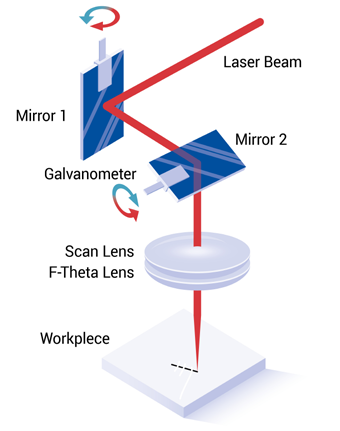
Figure 1. Schematic of a basic galvo scanner system. Image Credit: PI (Physik Instrumente) LP
3.1 F-Theta Lenses
The most popular lens type utilized in galvo scanners is an f-theta, due to their planar imaging field. Beam displacement is linear, following a simple f·θ relationship, where f is the effective focal length and θ is the deflection angle.
This method eliminates the need for intricate correction algorithms, making it easier to focus on a specific spot and helping to maintain an even scanning velocity and laser energy distribution.
F-theta lenses can be non-telecentric or telecentric. Non-telecentric lenses are usually lighter, but they cannot cause the light to hit the working surface orthogonally, adding an angular component to the field of view (FOV).
Telecentric lenses direct the beam to the workpiece at a 90 ° angle relative to the surface; however, they are larger, heavier, and costlier than their non-telecentric counterparts. Moving a telecentric lens demands stronger motion axes, ultimately restricting throughput due to acceleration requirements and longer move-and-settle times.
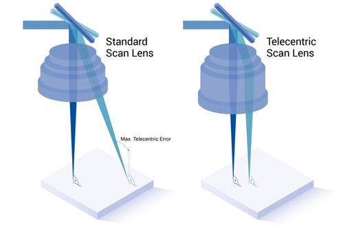
Figure 2. Telecentric error of a non-telecentric f-theta lens compared to a telecentric f-theta lens. Image Credit: PI (Physik Instrumente) LP
3.2 The Effect of the Field of View
Thanks to the low inertia of the mirrors, Galvo scanners can generate extremely high-bandwidth motion, enabling quick and easy acceleration and deceleration.
This enables substantially faster processing times than using an electric motor-driven positioning stage to move the workpiece beneath a fixed-point laser system. In most cases, galvo scanners will deliver the highest throughput over a moderately sized field of view, which is governed by the selected f-theta lens.
The aim of the laser system is to generate a spot size suitable for the application and to precisely position that spot on the workpiece within the field of view. The spot size is usually computed using the formula below:
Spot size = C × λ x f/A
Where λ is the wavelength of the laser, f is the effective focal length of the lens, A is the entrance beam diameter, and C is a constant (C = 1.83 for a Gaussian beam). The diagonal length L of a square area where the beam can be focused by the lens also depends on the focal length (f) and can be obtained from the following formula:
L = f × 2 θ
Where θ is the maximum deflection angle of the galvo mirrors. To increase the field of view, the effective focal length must be increased, assuming that the maximum angular deflection is fixed.
However, increasing the focal length also increases the spot size, as well as the physical lens size. In addition, it compromises effective system accuracy, since the encoders used for positional feedback by galvo motors possess a fixed feedback resolution, i.e., the smallest change in position the system is able to measure.
This reduces both the linear positioning ability and contouring smoothness at the workpiece, and can also present as f-theta distortions. Selecting a shorter focal length makes it possible to work around these effects and increase accuracy and resolution.
Another common approach involves restricting the galvo motor’s angular range, utilizing a small central portion of the FOV that is less impacted by distortions. The overall distorted projection stems from a combination of the pincushion effect, which is caused by the finite distance between the pivot points of each galvo mirror, and the f-theta barrel distortions.
Download the full article now to learn more
References and Further Reading
- Nakaoku, H. (2016). Precision processing with an ultrashort pulse laser processing machine. Panasonic Technical Journal, 62(2), 14–17. Available at: https://tech.panasonic.com/jp/phd/pdf/technology-journal/v6202/p0104.pdf.

This information has been sourced, reviewed and adapted from materials provided by PI (Physik Instrumente) LP.
For more information on this source, please visit PI (Physik Instrumente) LP.