Electron microscopy is a valuable tool for research and development, especially in the fields of electronics, photonics and material sciences. Modern scanning electron microscopes provide spatial resolution in the Angstrom range. Sub-nanometer precise mechanisms can aid with highly accurate and stable, drift-free positioning of specimens. Piezo-ceramic drive technologies are intrinsically non-magnetic and vacuum compatible - a decisive advantage.
High-resolution, electron-microscopic methods, shown in Figure 1, are used wherever optical investigation methods no longer suffice in structural investigations and where it is possible to have suitable specimen preparation. Their extremely high resolution could allow detection of the distances between individual atoms. Transmission electron microscopes (TEM) attain resolutions down to 0.1 nm, scanning electron microscopes (SEM) attain resolutions up to a range of 1 nm, and are thus significantly better than optical methods. Generally, confocal light microscopy achieves between 200 to 300 nm, optical super resolution with commercial systems achieves down to 20 nm.
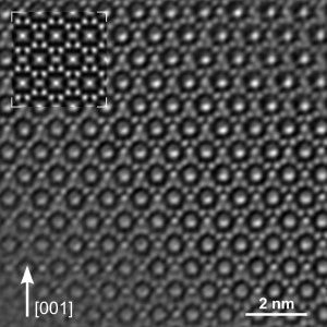
Figure 1. As the wavelength of the light is not a limiting factor in electron microscopes, even the distances between individual atoms can be detected. Transmission electron microscopes (TEM) achieve resolutions up to 0.1 nm, scanning electron microscopes (SEM) achieve resolutions up to a range of 1 nm (Image: Dr. Reiner Ramlau, MPI for chemical physics of solid materials)
Presently, there exists a wide range of typical applications for electron microscopy, extending much beyond research applications into industrial applications such as surface and structure inspection in Semiconductor Technology and Materials Research and also the field of Life Sciences. Even three-dimensional investigations are possible, in combination with an ion beam, whereby the ion beam removes individual layers of the specimen. In the case of tiny structures on semiconductors, this enables determining layer thicknesses by counting the number of superimposed atom layers. The tiniest cell structures are made visible in the field of Life Sciences. In this midst of other methods, it is possible to prepare the specimens with special freezing processes.
Stable Positioning and High Repeatability
All the different applications have one thing in common: increasingly automated inspection processes need reliable and flexible drive solutions which must work under conditions of vacuum and ideally be non-magnetic and lubrication-free. In the case of TEM, the specimen should be kept as stable as possible. Manipulation of specimens in the nanometer range is obligatory, after all, the viewing field is just 150 nm.
In the case of SEM (Figure 2), resolution directly relies on the position of the specimen. Repeatability and the stability of the positioning stages are considered to be crucial for the quality of the images as well as resolution, if the specimen is moved during the scan. Distortion of the images can only be avoided if no drift of the specimen takes place once the target position has been reached. The positioning stages should meet the highest requirements for smooth motion at velocities of a few nm/s. This indeed will allow moving of the exact positions on the sample surface with the highest precision and without any visible jitter when the EM image is monitored directly by the user. Piezo stepping drives are especially suitable here.
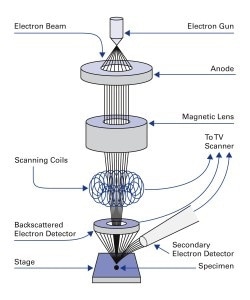
Figure 2. Principal design of a scanning electron microscope. (SEM) (Image: PI)
Piezo-Based Drive Solutions
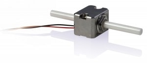
Figure 3. Mini-rod piezo inertia positioning drives are suitable for compact drive solutions, to adjust apertures for adjusting the electron beam or for tracking with other components. Piezo motion is also suitable during specimen preparation. (Image: PI)
Piezo-based drive solutions are capable of meeting all the above requirements of electron microscopy and a wide range of drives, multi-axis positioning systems and actuators, all of which are lubrication-free and vacuum-compatible are available. The piezo-based drive concepts produced in-house do not produce magnetic fields and are not influenced by them. This allows positioning systems to be assembled that are partly (except for the guiding) or fully (including the guiding) nonmagnetic.
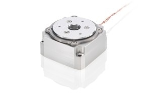
Figure 4. Compact, fast rotation stage based on ultrasonic piezo drive concept. (Image: PI)
For positioning tasks, simple actuators or drives can, for instance, be incorporated directly at the electron beam, where they are employed for correcting the beam guidance or for aligning apertures, as shown in Figure 3. Linear and rotation stages are ideal for positioning of the specimen, either for preparation before examination, for precise alignment in the beam path or for rapid scans. It is also possible to effortlessly combine these stages to multi-axis solutions. Rotary positioning of the sample is often needed in sample preparation for SEM. Shown in Figure 4 are compact rotation stages that permit the specimen to be transported rapidly, for instance, in dual-beam installations from the electron beam path to FIB analysis and processing. It is also possible to use the rotation stages for generating multi-axis sample scans in SEM or for altering the angles in crystallographic investigations (Electron Backscatter Diffraction (EBSD)). Linear stages with piezo-based drives (Figure 5) are specifically ideal for scanning specimens. Combined with a directly measuring high-resolution encoder, these stages permit extremely high-precision and repeatable positioning.
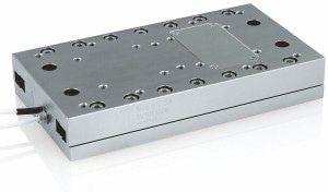
Figure 5. Sub-nanometer resolution linear stage with PiezoWalk linear motor and high resolution direct position measurement. (Image: PI)
Position Stability and High Reliability
What all piezo motor technologies have in common, is drift-free, stable position hold at rest, without additional power consumption. As a result, no heat is produced, which is beneficial, particularly in a vacuum environment. This makes piezomotors ideal for stable and precise positioning even during long downtimes. Simultaneously, drives are considered to be particularly reliable since they work as direct drives without any extra mechanical transmission components, such as gearheads. This rules out mechanical restrictions such as backlash, making the drive maintenance-free.
For all systems, appropriate control electronics and controllers are available which can be seamlessly incorporated into existing systems due to their digital and analog interfaces and the widespread software support. Several different piezo-based motor technologies are available as the requirements for positioning and drive solutions can differ significantly in the field of electron microscopy.
What is a Piezo Motor? How does it work? Piezo Motor Designs for Automation & Motion Control | PI
Different Piezo Motor Designs Video.
Matching Motor Technology to Requirement
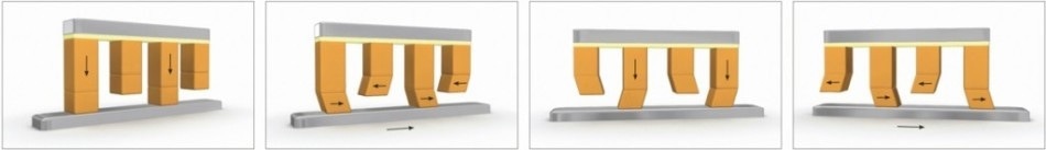
Figure 6. Functional principle of the PiezoWalk® motor technology: clamping and feed motion are distributed over separately driven longitudinal and shear actuators. A more compact and faster motor based on bending modes is also available. (Image: PI)
With PiezoWalk® stepping drives, piezo actuators work in pairs as feeding and clamping elements on a moving runner, as shown in Figure 6. Thus, cyclical control induces a stepping motion of the actuators on the runner, which, in turn, is moved backwards and forwards. PiezoWalk® stepping drives offer resolution and velocities to 10 mm/s.
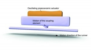
Figure 7. Ultrasonic piezomotors can provide very smooth, high resolution motion with a large dynamic range, from nanometers/second to 100’s of millimeters/second. (Image: PI)
Ultrasonic piezomotors, shown in Figure 7, are ideal for high feeding velocities and positioning tasks in the sub-micrometer range. The piezoceramic actuator is excited to ultrasonic vibrations with a high-frequency AC voltage between 100 and 200 kHz. Deformation of the actuator results in a periodic diagonal motion of the coupling element, relative to the runner. The high frequencies guarantee high velocities of several 100 mm/s. PI’s mini-rod inertia motor drives are also of interest for use with and in electron microscopes, as depicted in Figure 8. They are based on a single piezo actuator and make use of the stick-slip effect (inertia effect). Here, the piezo element generates cyclic alternation between static and dynamic friction between a moving runner and the actuator. With an operating frequency of more than 20 kHz, this produces a continuous feed of the runner at velocities of more than 10 mm/s at nanometer precision levels. Piezo-based drive and positioning solutions are ideal for all requirements in electron microscopy because of the variety of piezo motor technologies.
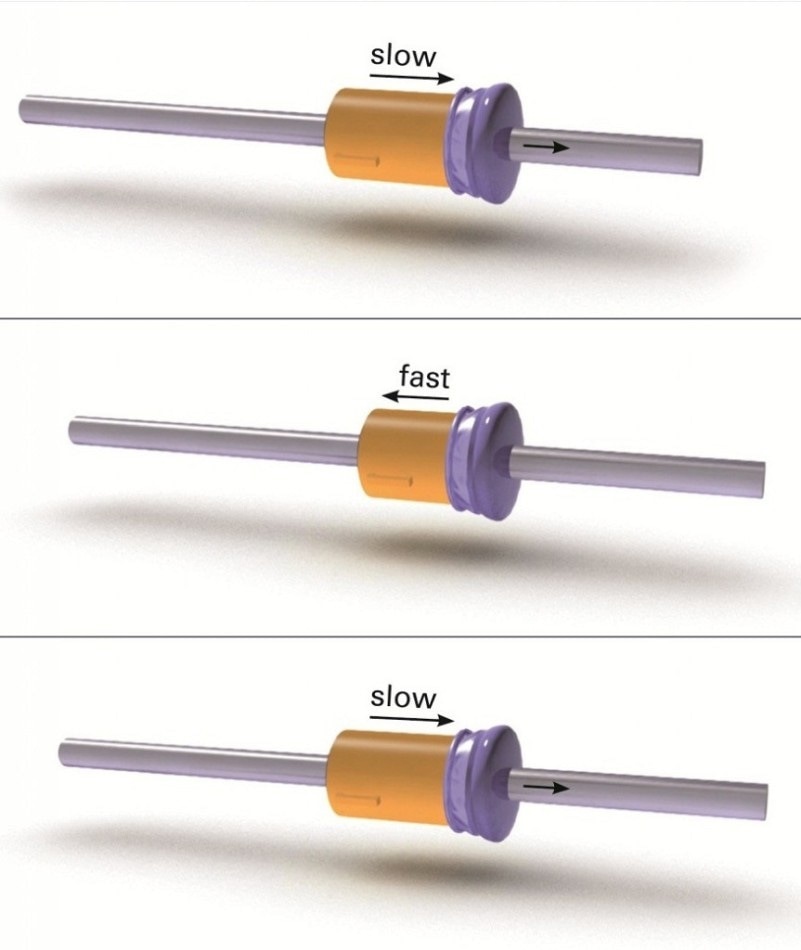
Figure 8. PI’s mini-rod piezo inertia motor principle is based on a single, low-voltage piezo-stack actuator. The actuator expands slowly taking along the runner. When the piezo element contracts quickly, the runner cannot follow due to its inertia and remains at its position. (Image: PI)

This information has been sourced, reviewed and adapted from materials provided by Physik Instrumente (PI) GmbH & Co KG - Worldwide.
For more information on this source, please visit Physik Instrumente (PI) GmbH & Co KG - Worldwide.