The form of highly sloped surfaces has always been a challenging application for optical profilers using coherence scanned interferometry (CSI). In fact, highly sloped surfaces exist in almost every industry, for example brightness enhancing structures, optical micro-lenses and machined cones.
The capability to obtain valid topography data from high slopes is enabled by advances in signal detection and processing features available on ZYGO’s CSI-based profilers running on Mx™ software.
Theoretical Limits
The theoretical limit for a slope capability of a given microscope objective is based on the lens’ numerical aperture:
arcsin(NA) = maximum angular acceptance
Generally, a high NA lens also serves as a high magnification lens. The dependence of slope limitation on NA is a crucial factor here, because it indicates that high magnification is not adequate to achieve the highest possible slope resolution.
For example, a 0.7 NA objective lens with 100x magnification has a maximum slope acceptance of 44 degrees, while an objective lens with a 0.85 NA and the same 100x magnification has a maximum slope acceptance of 58 degrees, an improvement of more than 30%.
The formula provides a maximum theoretical acceptance angle for a specular test surface - a level which is not easy to achieve in practice. When the surface slope is increased and it approaches the theoretical limit, the strength of the light returning to the interferometer weakens.
This creates a low contrast interference signal, which is sometimes can hardly be distinguished from the background illumination from the reference surface of the interferometer. The signal’s weak nature is the main reason why CSI profilers that find it difficult to measure highly sloped specular surfaces.
In some cases of non-specular surfaces, the theoretical limit can be exceeded by over 50% because of the surface’s scattering structure. Using the 100x 0.85 NA lens mentioned above, angles as high as 87 degrees can be measured on a machined surface on the Nexview™ profiler.
Overview of ZYGO Nexview™ NX2 Non-Contact Optical Profiling System
In Practice on a Smooth Surface
For sample measurements, a rectangular glass rod with very sharp right angles was used as a test piece. When the rod is placed on the V-Block, it presents the edge of one of the corners to the system such that each face is at 45 degrees with regard to the interferometer reference surface. The NewView™ 8000 profiler running on Mx™ software uses the 100x 0.85NA lens to measure this surface without any major difficulty in about 15 seconds, as shown in Figures 1 and 2.
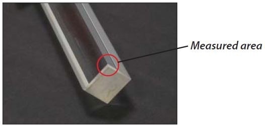
Figure 1. Quartz rod with near perfect 90° corners.
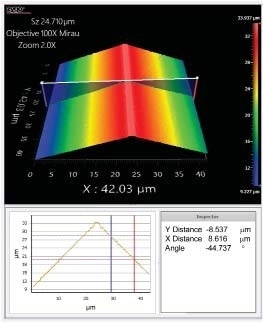
Figure 2. 45° slope measured on the Nexview™.
Rotating the V block by 10 degrees presents the corner such that one surface is inclined away, at an angle of 55 degrees, which is close to the theoretical limit of 58 degrees defined earlier. The interference pattern has such a weak signal strength that a measurement using standard settings fails to detect the surface, but profilers running on Mx™ software can employ the “Dynamic Noise Reduction” method to decrease signal noise and reduce the measurement speed , thus making it possible to detect the weak signal.
Using a reduction factor of 6x for this measurement, the surface was measured in 350 seconds, as shown in Figure 3. Although the surface can also be detected using smaller noise reduction factors, this can lead to more loss of data.
The exact level of dynamic noise reduction is a tradeoff between measurement throughput and data density. If there is a need for a less detailed structure data, a lower noise reduction factor can be selected to maximize the surface.
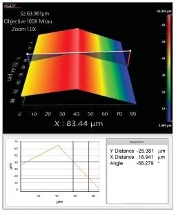
Figure 3. Quartz rod tilted 10° to present one surface at 56°.
In Practice on a Rough Surface
Theoretical specular limits do not account for the substantially higher surface angles which occur when measuring a rough surface.
The commercial razor blade is a good example. The blade surface possesses a surface slope of about 60 degrees, but has a highly distinct structure. The surface is similar to the glass rod and can be tilted further away using a rotation fixture.
This is demonstrated on a Nexview™ profiler with the blade rotated such that the surface has a slope of 86 degrees. Figure 4 shows the result of this measurement, which was done in 133 seconds using 3x Dynamic Noise Reduction and a 100x 0.85 NA lens.
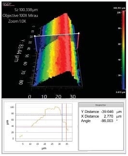
Figure 4. Commercial razor blade measured on edge shows a measurable surface slope of 86°.
Conclusion and Next Steps
Featuring algorithmic advances and measurement techniques, ZYGO’s CSI profilers which run on Mx™ software offers considerable improvements in measuring steep slopes.
In majority of cases, the measurement capability is close to the theoretical limit, and on rough surfaces, this theoretical limit can be exceeded, Due to variation in different types of surfaces, ZYGO specifies profilers that provide more conservative performance than the examples seen above.
The new tools are useful for applications requiring high slope metrology for angle and form measurements. They can provide a lot more quantitative data in a shorter time frame without damaging the parts, when compared to other competitive, non-interferometric methodologies.
ZYGO recommends a free application evaluation to check whether such enhancement will solve specific slope challenges. ZYGO profiler applications engineers can be contacted for an evaluation or more information.

This information has been sourced, reviewed and adapted from materials provided by Zygo Corporation.
For more information on this source, please visit Zygo Corporation.