An unproductive settlement has to be made between satisfactory throughput and adequate data coverage when measuring high-slope machined components. This is because metrology tools involve some type of tradeoff between slope acceptance and measurement speed. For example, for optical systems, while higher-NA objectives possess higher slope acceptance, they typically possess smaller fields of view (FOV). This results in additional individual measurements if the region of interest surpasses a single FOV.
Large-departure and recessed features create an additional challenge of imposing a minimum working distance. This also usually involves a compromise with slope acceptance.
Machined parts are commonly measured using coherence scanning interferometry (CSI). CSI provides non-contact areal topography maps with usual single-measurement topography repeatability of less than one nm on smooth, high-reflectivity surfaces [1]-[2]. A selection of objective magnification differs from approximately 1X to approximately 100X. Preferably, the maximum local slope θmax falls within the specular limit of the objective NA so as to fulfill the condition, NA > sin (θmax). In reality, a lower-NA objective may be needed due to the restrictions of minimum working distance or field-size/throughput, or because of cost and availability issues. Fortunately, quantifying slopes outside the specular limit can be enabled if some light is scattered (typically by surface roughness) and the measurement is sufficiently sensitive. However, it is difficult to measure high-slope parts by CSI, even in such conditions.
The latest technological developments considerably increase the baseline sensitivity of CSI and enable high-dynamic-range operation. This enables the measuring of high-slope or recessed features that were previously inaccessible, or larger FOVs for improved throughput.
Measurement and Analysis
An advanced commercial CSI microscope was used to measure a variety of machined parts [3]. Figure 1 illustrates the process of CSI, which functions by scanning an interferometric objective corresponding to the sample being measured, producing localized interference patterns defining sample heights at all pixels of the camera. Areal topography data is produced by a single scan at corresponding positions of best focus, over the full field of the camera. Any type of interferometric objective can be used, including Mirau, Michelson, Linnik, or wide-field [4]-[5].
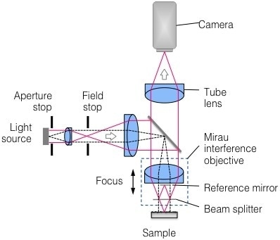
Figure 1. Schematic representation of Coherence Scanning Interferometry.
The baseline data acquisition time for the results seen in this article is around 0.14 seconds per micron scanned. Raw height data is shown in all surface plots, without any smoothing, masking, or interpolation of missing data points. Dynamic noise reduction (DNR) was used to detect weak signals, allowing a user-specified compromise between throughput and sensitivity, while maintaining complete lateral and vertical resolution [6].
Slopes Beyond the Specular Limit
Figure 2 is a diamond-turned cone with an included angle of 90°, where the cone has an outermost diameter of 4 mm, and relatively low surface roughness (Sa~ 1.1 nm, as measured at normal incidence with a 10X Michelson objective). An objective with NA > 0.7 would be required to lodge the 45° slopes within the specular limit. This would involve stitching hundreds of FOV, with undesirable throughput.
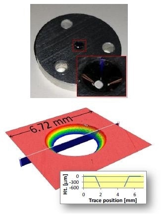
Figure 2. Measurement of 5-mm-diameter diamond-turned 90° cone in a single FOV. Top: photograph of part; bottom: measured height map.
A low-mag objective with NA below 0.7 is required to measure the cone within a single FOV. Using traditional CSI for such a measurement may generate a small amount of data. It also shows that data at slopes over the specular limit allow for the detection of scattered light.
Almost-full data coverage can be accomplished by using a 2.5X Michelson objective (NA = 0.075) along with 4X DNR (16X increase in baseline measurement time). This data is ideal for measuring cone angle and roundness.
Spherical features have slopes of nearly 90°, and are found in a variety of applications, such as ball bearings and sealing surfaces. Measurement of spherical features becomes more difficult with expanding diameter: high slopes are required for increasing FOV and working distance.
Figure 3 shows a 3-mm-diameter fuel-injector sealing ball, as measured in a single FOV with a 5.5X Michelson (NA = 0.15). Almost full data coverage is accomplished for local slopes of more than 60°. The same objective is used to measure surface roughness (Sa), which is approximately 0.1 µm.
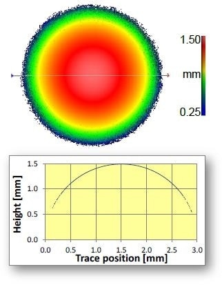
Figure 3. 3-mm-diameter sealing ball measured in a single FOV for local slopes up to 60°.
Even if stitching has to be done, access to larger FOVs is beneficial. These include enhanced throughput, and quicker targeting of functional surfaces and registration to datum surfaces. Using lesser FOVs also decreases the form error, caused by stitching numerous slivers of data from smaller-aperture height maps.
Figure 4 shows a diamond end-mill [7] exposed to wear in three locations and producing local slopes over 70°. It may look like this involves stitching hundreds of high-NA measurements. However, comprehensive data coverage was accomplished by stitching just ~20 FOVs employing a 20X Mirau objective (NA = 0.4, specular limit ~23°), resulting in 0.4-µm lateral sampling (0.9-µm optical resolution) and nm-scale vertical resolution over the total tool length with a total measurement time of just nine minutes.
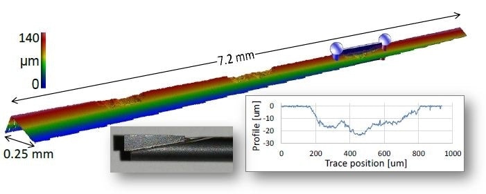
Figure 4. End-mill measured with 0.4 µm lateral sampling over 7.2-mm length and 145-µm scan range in about 9 minutes. Photograph of part is shown in lower left inset.
Success in measuring slopes over the specular limit depends upon a number of factors, including spatial-frequency-dependent variations of the surface roughness and the Sa of the sample.
Recessed High Slopes
At times, high-slope features are recessed, residing at a certain distance below an adjacent feature. Common instances include shoulders along the exterior of a shaft and cones inside bores. Recessed features serve as mounting or sealing surfaces, with equivalent critical parameters such radius, roundness, and angle.
An objective with sufficient working distance for accommodating the recess depth is required to optically measure these important parameters. This decreases the options to lower-NA objectives, which forcing measurements to be taken using any scattered light available. Using traditional CSI would be impractical to measure some extreme cases of recessed high slopes.
Figure 5 shows a photograph of an unfinished fuel injector with surface roughness Sa~ 1 µm. A shoulder in which the fuel injector mounts against an engine block is shown by the highlighted region. This shoulder’s geometry is an important factor to guarantee proper sealing, and can be characterized by the circumferential radius that is developed at the intersection of two steep-slope regions.
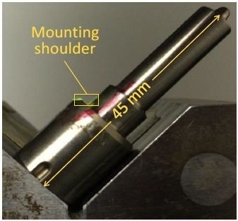
Figure 5. Photograph of fuel injector, with mounting shoulder region outlined in yellow.
Previously, the measurement of the shoulder region would have involved stitching a number of higher-magnification measurements, as well as avoiding mechanical interference with the rest of the part. Figure 6 illustrates a measurement captured in a single FOV of a specialized 5X Michelson (NA = 0.12) with a working distance of 40 mm. Almost-full data coverage is realized despite local slopes up to 45°.
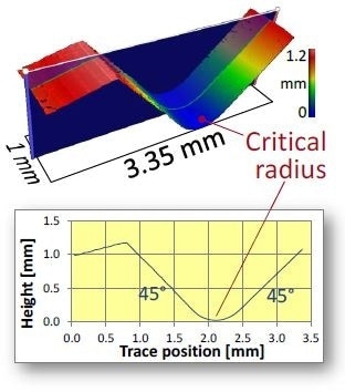
Figure 6. Measurement of shoulder region of fuel injector, highlighting radius critical for proper sealing with engine block.
An electrical feed-through assembly comprising of a number of ~ 1-cm pins, secured by glass cladding that is recessed by ~ 1 mm within a metal housing, can be seen in Figure 7. Other than the obstructing pins, the difficulties in the measurement of the glass profile include moderately weak scattering, due to low roughness, refractive index, and moderate local slope up to ~ 15°.
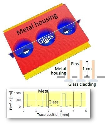
Figure 7. Electrical feed-through assembly. Of primary interest is the glass cladding, recessed below the metal housing along with pins extending ~1 cm beyond the housing. Blue regions in the height map correspond to glass, with missing data indicating the location of pins.
Using a 5.5X Michelson (NA = 0.15) results in almost-full data coverage of the glass cladding, with missing points corresponding chiefly to the location of the encased pins. A high dynamic range (HDR) mode was used, combining scans at varying light levels [6] so as to efficiently control the wide range of part reflectance (tilted glass vs. metal).
Near-Vertical Slopes
Highest measurable slope is a function of objective NA, along with the effective reflectivity of the surface being measured. The examples discussed in this article have been related to measurements using lower NA objectives. It would be interesting to learn how high measured slopes become at a higher NA.
For a hypodermic needle measured end-on in a single FOV using a 50X Mirau objective (NA = 0.55, specular limit ~33°), the measured slope is at random close to vertical, as illustrated in Figure 8. On all beveled surfaces with current slopes of 74° and 82°, data is acquired. Data is also acquired along the near-vertical outer tube surface in which the slope is beyond 89°. Like before, there is no need for interpolation or masking, and there is no false data in the bore region.
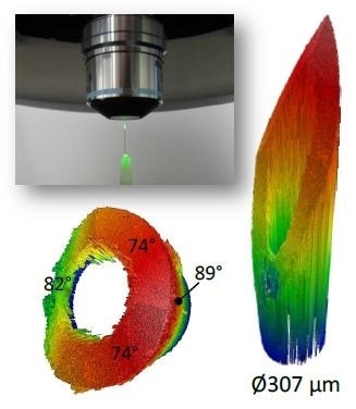
Figure 8. Hypodermic needle measured end-on in a single FOV. Upper left: photograph of setup. Right: obtained data over 1.8-mm scan range. Lower left: same data rotated to show measured slopes up to 89° and automatic identification of bore region.
Conclusion
Due to the latest technological progress to enhance sensitivity of weak interferometric signals, recessed and high-slope features can be measured via CSI, which was previously not possible. Other than enhancing baseline sensitivity, the technological progress includes tools to lengthen dynamic range such as DNR and HDR [6]. As the examples in this article reveal, measurement of even 89° slopes has been made possible.
The enhancements also allow broader latitude in objective selection, operation over larger FOVs for improved throughput and larger working distances for ease of use.
Acknowledgments
The original work presented in this paper benefited from key contributions and input from Eric Felkel, Nate Gilfoy, Mackenzie Massey, and Dan Russano.
References
[1] de Groot P. Coherence Scanning Interferometry. In: Leach R, editor. Optical Measurement of Surface Topography. Berlin: Springer Verlag; 2011. p. 187- 208.
[2] ISO, [25178-604:2013(E): Geometrical product specification (GPS) – Surface texture: Areal – Nominal characteristics of non-contact (coherence scanning interferometric microscopy) instruments] International Organization for Standardization, Geneva (2013).
[3] Zygo Corporation, [NexView Optical Profiler], Specification sheet SS-0095 09/12 (2013).
[4] J. Biegen, X. Colonna de Lega and P. de Groot, "Wide-field interference microscopy for areal topography of precision engineered surface," Proc. ASPE annual meeting, paper 4111 (Boston, 2014).
[5] P. J. de Groot, L. L. Deck, J. F. Biegen and C. Koliopoulos "Equal-path interferometer", US Patent 8,045,175 (2011).
[6] Fay, M. F., Colonna de Lega, X., and de Groot, P. Measuring high-slope and super-smooth optics with high-dynamic-range coherence scanning interferometry. Proc. OSA, 2014: Paper 1981102.
[7] Thanks to Professor Chris Evans and Chris Tyler at the University of North Carolina at Charlotte (Mechanical Engineering and Engineering Science).

This information has been sourced, reviewed and adapted from materials provided by Zygo Corporation.
For more information on this source, please visit Zygo Corporation.