Brushless servo motors are all the hype these days. But stepper motors still provide a number of advantages while being more cost efficient and robust. Together with precision linear and rotary positioning mechanisms, stepper motors can improve and automate many processes in micro-manufacturing, life-sciences and optics test and assembly. The article shows what impressive accuracy and performance can be achieved in precision motion and positioning applications with stepper motors and modern controllers.
Basic operating principle of a stepper motor. (Image: Wikipedia)
Stepper motors have the capacity to take discrete positions of constant distance. The most widely used stepper motors are two phase/four phase motors with 200 to 500 full steps per revolution. Advanced controllers can interpolate thousands of microsteps between each full step to accomplish higher resolution. A controller commands a position by issuing multiple electric pulses. Position feedback is not needed, but can help to enhance performance. If position feedback is not used, parameters such as highest acceleration have to be taken into consideration to avoid stalling the motor during acceleration. A mechanical damper on the motor shaft, which also serves as a handwheel, supports smooth operation and helps to realize better dynamics. A combination of appropriate linear measuring systems and high-resolution controllers boosts the positioning repeatability.
Stepper motors can hold a position very steadily, without jitter, but current must be applied constantly unless self-locking gearboxes/screw drives or brake mechanisms are used. Stepper motors can heat up during (nonstop) operation and this must be considered when designing a system.
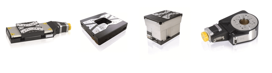
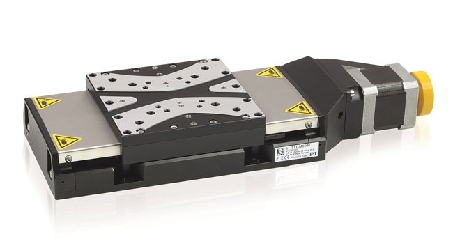
Several stepper motor driven precision positioning stages from PI miCos: (left to right) L-511 linear stage (former PRS-110), MCS Planar XY stage, L-310 Z-axis stage (former ES-100), L-611 rotation stage. (former PRS-110) (Image: PI miCos)
Precision Positioning, Down to the Nanometer Range
A linear positioning stage fitted with a 2 mm lead screw, driven by a stepper motor with 200 full steps (1.8° per step) delivers linear motion in 10 µm increments for each motor step. This is barely considered precision motion in the 21st century and microstep controllers can optimize the performance significantly. A simple microstepper with 16 microsteps already helps to reduce this number down into the sub-micron range at 0.625 µm and 39 nm are calculated for a 256 interpolation factor. It must be remembered that low friction mechanics are necessary to attain this calculated resolution in the real world.
Higher interpolation means smoother motion and improved resolution and cost-effective controllers such as the C-663.12 Mercury Step already offer 2048 microsteps. Advanced controllers, such as the SMC Hydra, provide virtually continuous, step-less behavior akin to a brushless motor. Besides higher position resolution, dynamic velocity and acceleration range, vibrations that are present in complete step mode are now almost absent.
Combined to a high-precision, low friction mechanical positioning stage, stepper motors can attain linear resolution in the nanometer range, even when functioning without the help of position feedback such as a linear encoder.
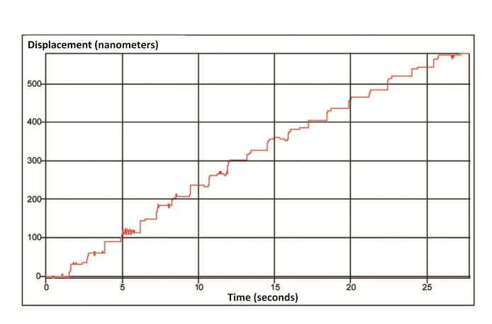
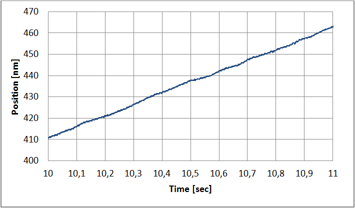
Shown above, repeated 25 nm steps measured with a laser interferometer: performance of an L-509 (below), entry level precision positioning stage operated in open loop (no position feedback. The stage is equipped with a 2-phase stepper motor (200 full steps) and 1mm ball screw and driven by an SMC Hydra controller with 3000 microsteps. (Image: PI miCos)

Position Feedback Improves Repeatability and Linearity
Position feedback, in the form of a direct-measuring linear encoder, can further improve the repeatability and accuracy. Drive train errors caused by backlash and friction in the gear-box, drive screw or the guiding system are at present seen by the controller and can be compensated for.
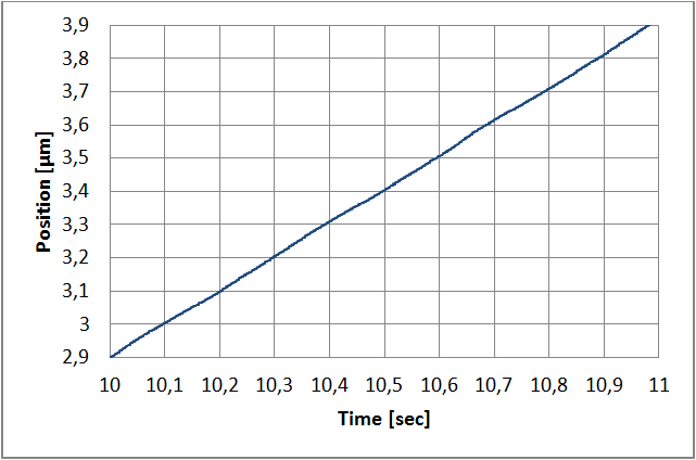
Shown above, closed-loop performance: 10-nm steps of an L-511 linear stage (below) with 2-phase stepper motor, with linear encoder. Even steps as small as 10 nm steps can still be resolved, the repeatability for a motor/screw-drive system is remarkable. (Image: PI miCos)
Stability and Resolution of Closed-Loop Steppers Compared to Servo Motors
Position-controlled stepper motor axes are recognized for outstanding position stability. Traditional classical (DC) servo systems exhibit typical controller oscillation up to a few encoder counts. For low-friction, low-damping situations, this can result in instability if the servo parameters are not fixed carefully.
A standard servo system feeds off errors, i.e., it has to see an error before it responds. These effects do not happen with a stepper motor, as it does not need the servo to maintain a steady position. In fact, when a current is applied to the stepper motor, it produces a moment that maintains it in place, while a servo motor wants to shift the moment a current is applied. Stepper motor controllers provide an intrinsic velocity feedforward, which allows them to work at highly constant velocity, even at very low speeds, without the support of an extra tachometer.
However, if the microstep resolution of the controller is very low, a difference between the motor and the encoder resolution can result in a quantization of the achievable positions. With regards to the SMC controller with 3000 microsteps, the angular motor positions are practically continuous – for a 1 mm drive screw, the calculated resolution is 1.6 nanometers- typically below the achievable resolution of a positioning stage with mechanical bearings.
Shown above, incremental linear encoders are often used for position feedback and position information is usually transmitted as analog sine-cosine signals with an output range of 1 Vpp, then digitized and interpolated in the controller down to the nanometer range and below. The measurement above shows the performance of a reference class linear encoder (model PIOne, at 400 kHz bandwidth and 18-bit resolution): 16 pm RMS and 100pm peak-to-peak are feasible. (Image: PI miCos)
Step-and-Settle Behavior
Good step-and-settle behavior is essential for high throughput and time-based processes. Besides the mechanical design, the control algorithms have a strong impact on the performance. SMC controllers suppress high frequencies and yet allow dynamic positioning with marginal overshoot, preventing oscillations and side effects for the overall stability of the system.
The mass of the payload, the resulting moments, and the orientation of the motion axis must be considered when improving the control parameters. Additional measures are not needed; the system is stable, and optimized dynamically.
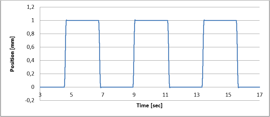
1 mm steps, executed by an L-511 with position control. (velocity 15 mm/s; acceleration 200 mm/s2) (Image: PI miCos)
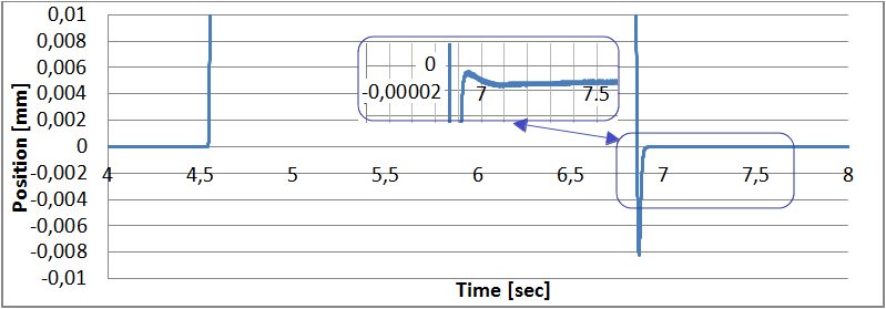
Zoomed view shows overshoot of less than 10 µm. The insert shows that only one single oscillation occurs. The target position is reached within a few tenths of a second within a window of less than 20 nm. (Image: PI miCos)
Constant Velocity at Low Speed Motion
Velocity is a decisive parameter for choosing a positioning system. Frequently, the highest speed is what counts, but, some applications require particularly slow constant motion. In a few scientific applications, velocities can range from a few 100 µm/second to substantially less than 100 nm/second, corresponding to a feed of a few millimeters per day. To realize very uniform motion, a positioning system with a resolution about one nanometer is suggested.
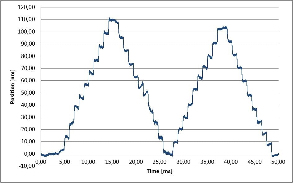
Velocity constancy at 1µm/sec, measured with L-511 stage in closed-loop mode. (Image: PI miCos)
Velocity constancy at 50 nm /sec, measured with L-511 stage in closed-loop mode. (Image: PI miCos)
Influence of Microstep Count on Noise and Position Deviation
The number of microsteps in a controller has an impact on the smoothness of motion. A higher microsteps count results in lower vibrations and better velocity constancy.
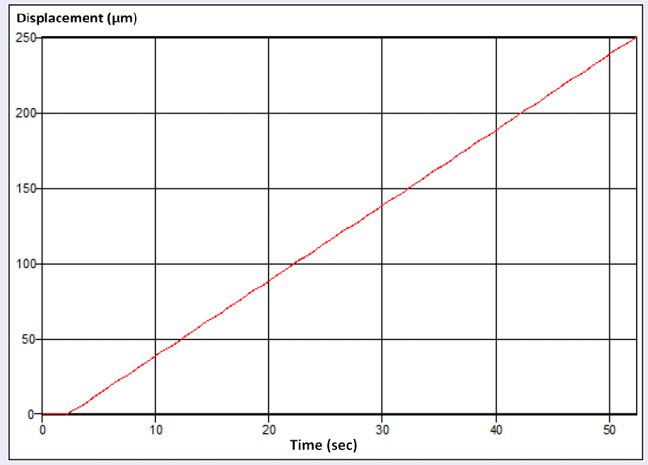
Shown above, constant velocity at 5 µm/sec (open loop). L-511 linear stage with SMC Hydra motion controller (3000 microsteps per full step). At this low-detail level, the performance with a 16 microstep controller looks nearly identical. (Image: PI miCos)
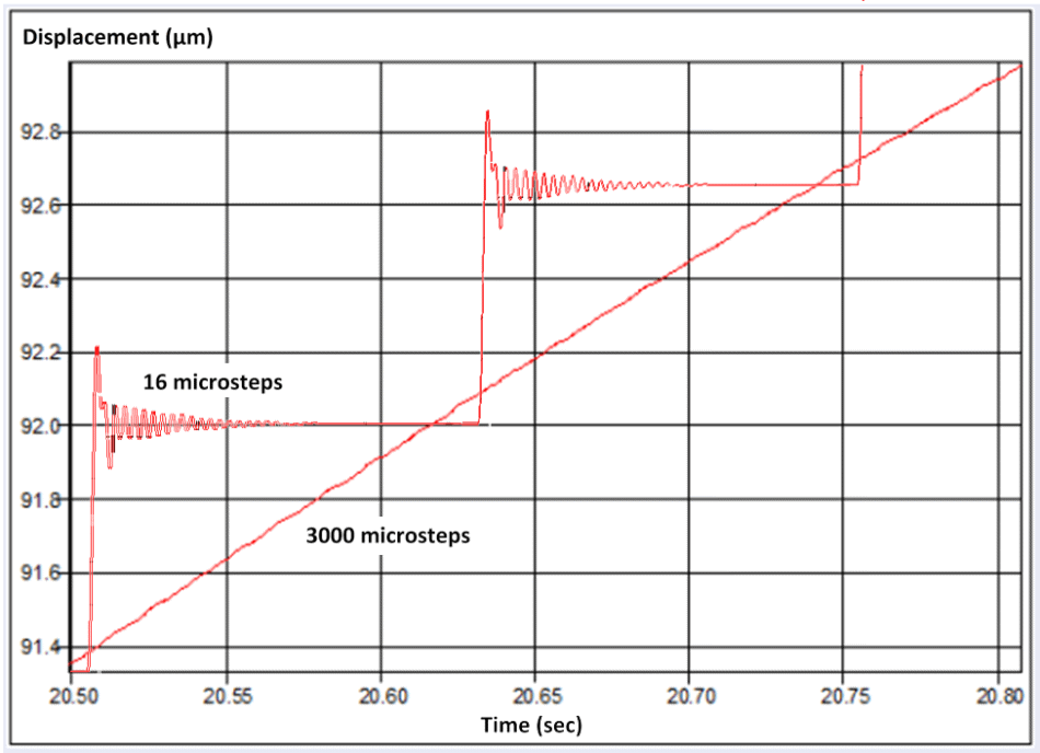
Shown above, this detailed view shows a big difference. The 16 microstep controller cannot resolve below 0.6 microns and each step is clearly visible at this resolution. The 3000 microstep controller performs smooth motion with almost perfect straightness. Tests in closed loop operation have shown additional improvements. (Image: PI miCos)
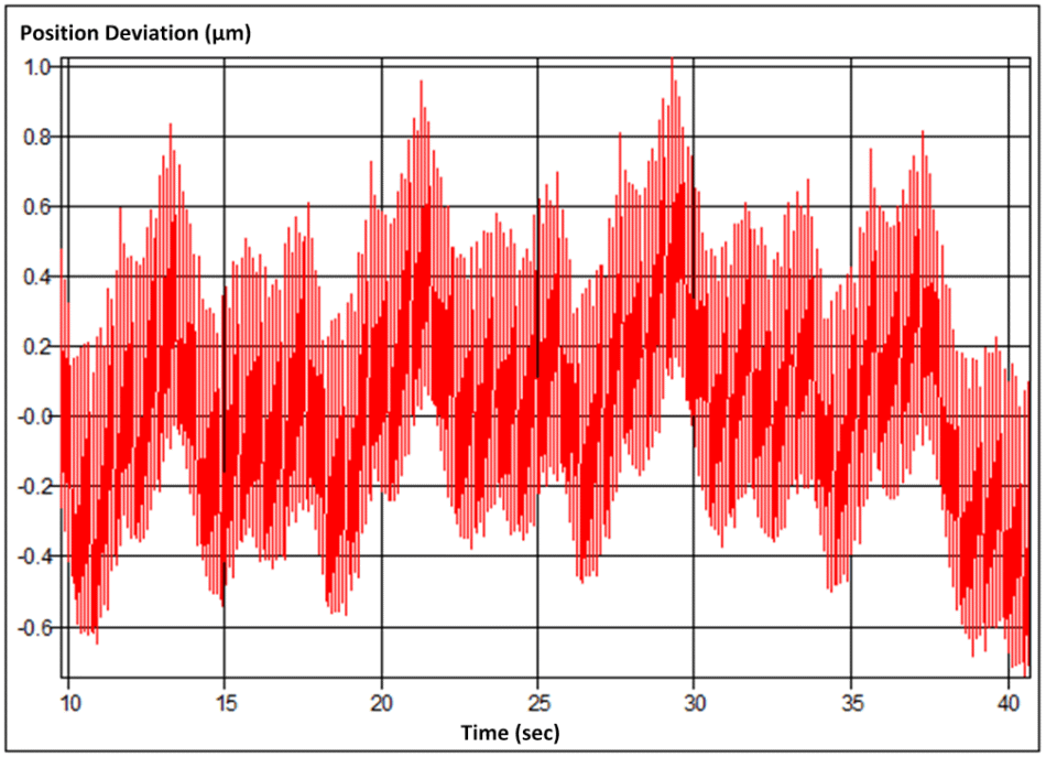
Shown below, 16 microstep performance in constant velocity mode (open loop): position deviation compared to ideal target position based on constant velocity. Note, the peak-peak deviation is only 1.5 µm. The controller’s limited resolution of 0.6 µm is largely responsible for behavior shown below. (Image: PI miCos)
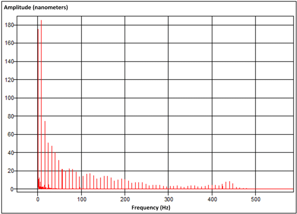
Shown above, FFT: Frequency spectrum of the position deviation of the 16 microstep controller. (Image: PI miCos)
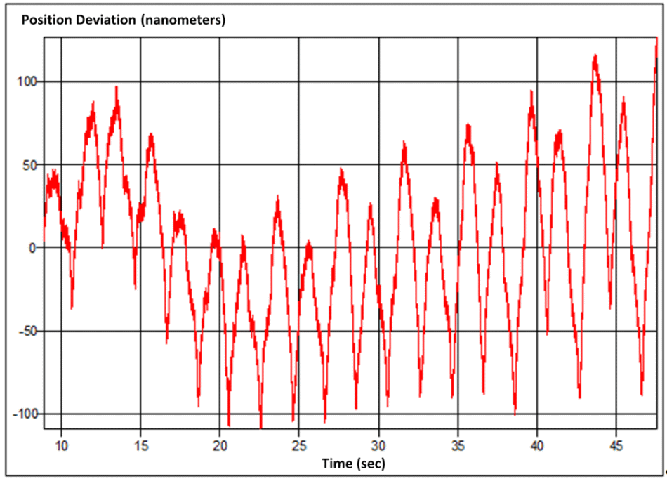
Show above, position deviation compared to ideal target position based on constant velocity with 3000 microstep controller (constant velocity mode, closed-loop): the high resolution microstep controller shows significantly improved performance compared to the 16 microstep behavior. (Image: PI miCos)
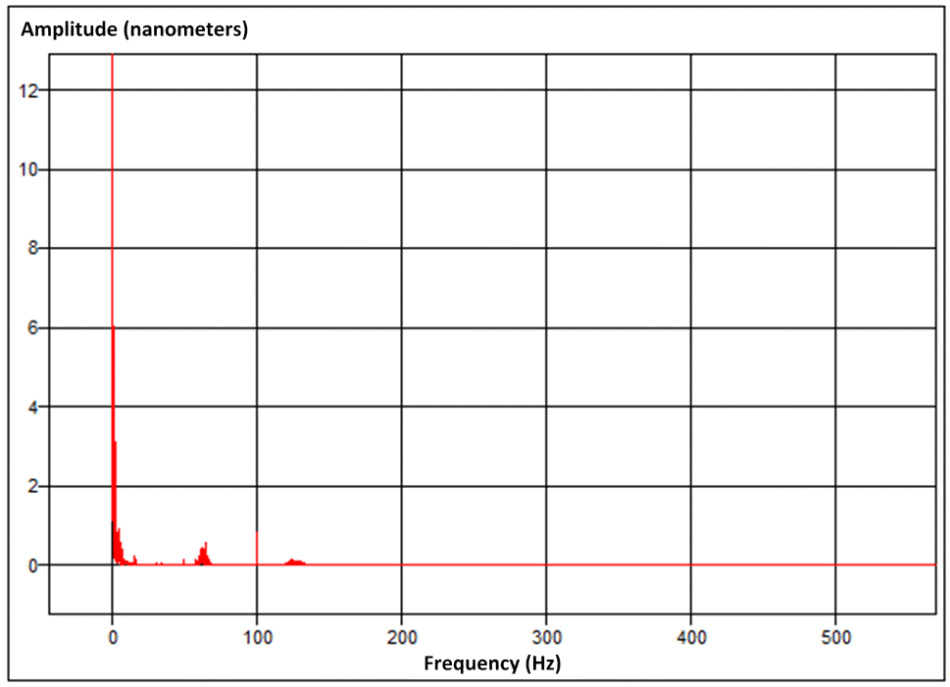
Shown below, FFT: Frequency spectrum of the position deviation of the 3000 microstep controller (Image: PI miCos)
Dynamic Position Correction (Error Mapping)
Error mapping (dynamic position correction) is a common method to enhance the overall accuracy of rotary and linear positioning stages. Improvements up 1000 % are achievable.
For this reason, the deviation from the target position at a predefined step size is measured using a reference measuring system. The measured deviations are stored in a table within the controller. During operation, the controller dynamically applies the data collected from the reference system and applies a correction factor for each target position correcting the motion profile on the fly.
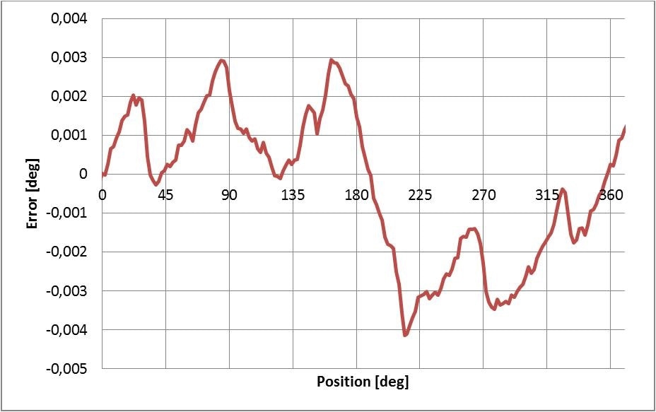
Shown above, the absolute accuracy of a closed-loop L-611 /PRS-110 rotation stage (below) with stepper motor and angle-measuring system, recorded over 360 individual positions spaced at 1°. The maximum angular error amounts to ±0.004°. (Image: PI miCos)
Shown below, the same stage as before, but with an active error map stored in the SMC Hydra controller for dynamic error correction. The symmetrical behavior independent of the direction of rotation is clearly visible. The maximum angular error is reduced to ±0.0003°. (Image: PI miCos)
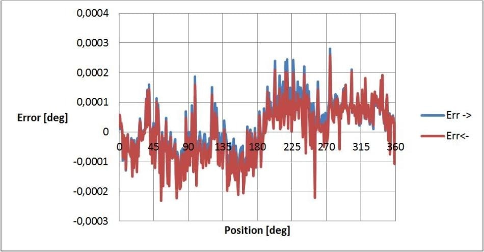
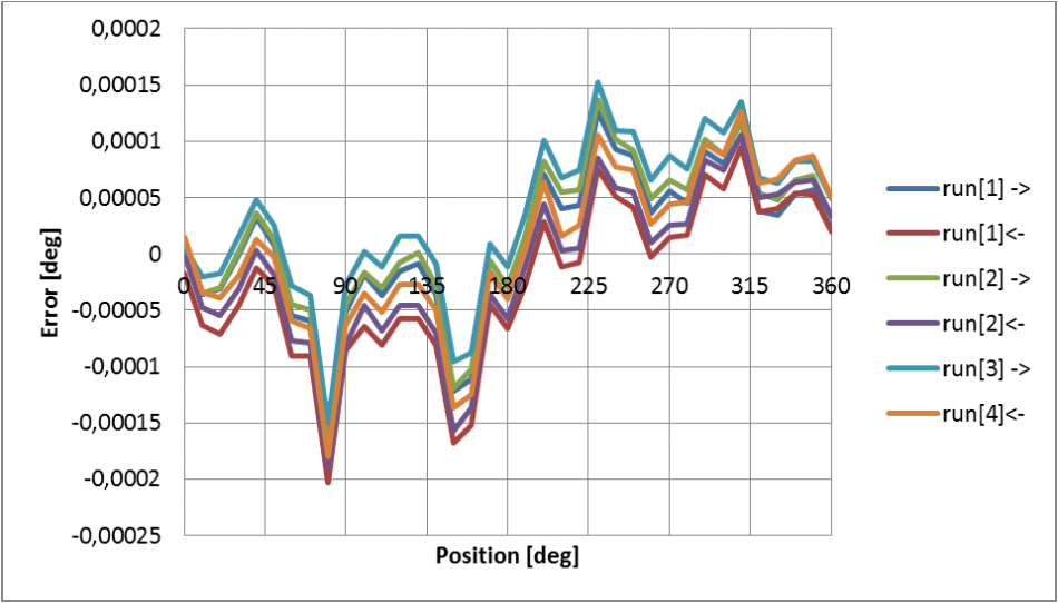
Shown above, error mapping also improves the bidirectional repeatability. (Image: PI miCos)
Measurement Set-Up, Ambient Conditions, Test Equipment
All measurements were conducted under standard lab conditions, humidity 43% ±3% and temperature 22 °C ±1 °C. A vibration isolated table was used, but no further isolation from acoustic, thermal or other external influences. Ambient conditions can have a strong impact on the attainable precision. For a common positioning stage made of aluminum, a 0.01 °C fluctuation of the ambient temperature corresponds to a position change of 10 nm. A stable environment is a standard requirement for precision motion in the sub-micrometer range. The user of special material pairings can assist, too.
The following measurement equipment was used:
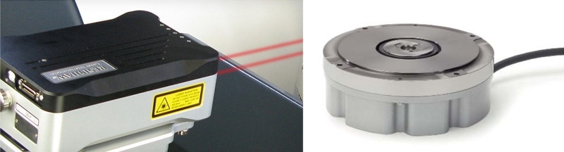
(left) Linear measuring device: Renishaw XL-80 interferometer, with reference mirror 25 mm above the motion platform. (Image: Renishaw)
(right) Rotational measuring device: Heidenhain RON-905. (Image: Heidenhain)
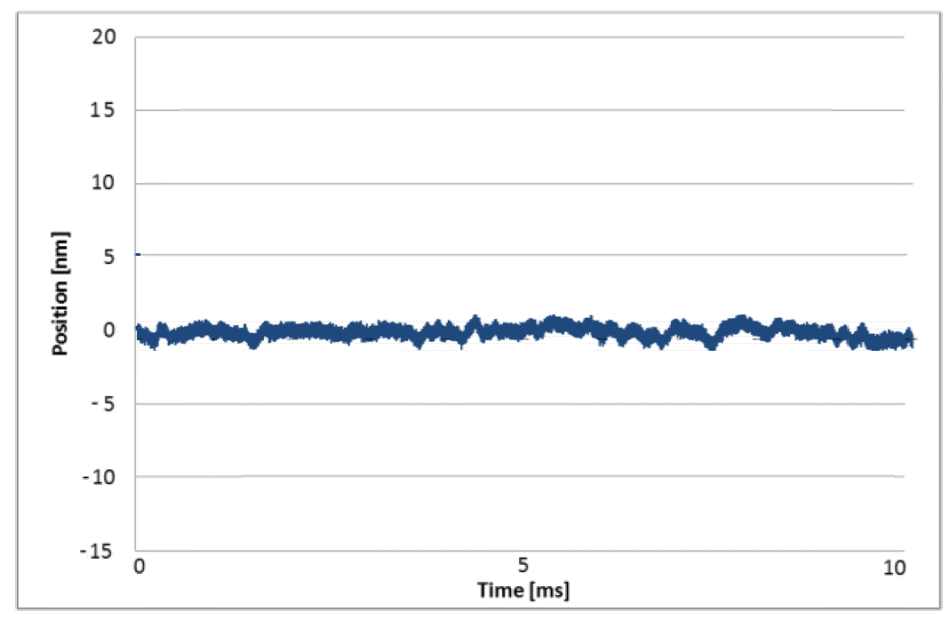
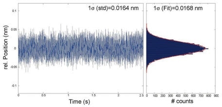
Shown above, the position noise of a L-511 linear stage, with energized motor, driven by the SMC Hydra controller in closed-loop mode. The noise level is at approximately 3 nm (peak-peak, 10 kHz sample frequency, unfiltered) which can be attributed to the interferometer and environment during the time of the measurements. (Image: PI miCos)
Positioning Systems and Motion Controllers
The following standard linear and rotation positioning systems and controllers were used for the above tests.
- L-511 Linear Stage (formerly LS-110) open and closed-loop versions
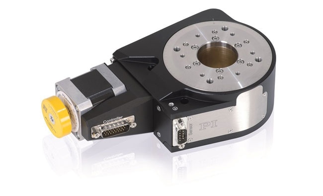
- L-611 (formerly PRS-110) open and closed-loop versions
- L-509 (formerly PLS-85) open and closed-loop versions
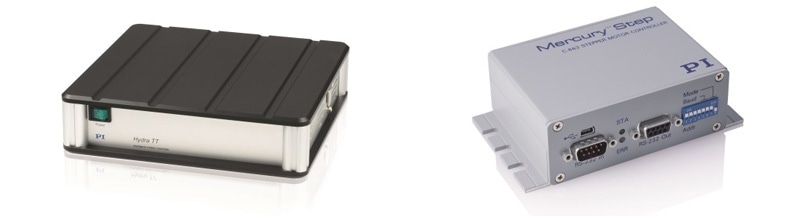
(left) SMC Hydra controller, 3000 microsteps per full step with integrated DeltaStar Eco encoder interface module (1 Vpp sin/cos input). (Image: PI miCos)
(right) C-663.12 Mercury Step, compact economical controller with 2,048 microsteps. (Image: PI miCos)

This information has been sourced, reviewed and adapted from materials provided by Physik Instrumente (PI) GmbH & Co KG - Worldwide.
For more information on this source, please visit Physik Instrumente (PI) GmbH & Co KG - Worldwide.