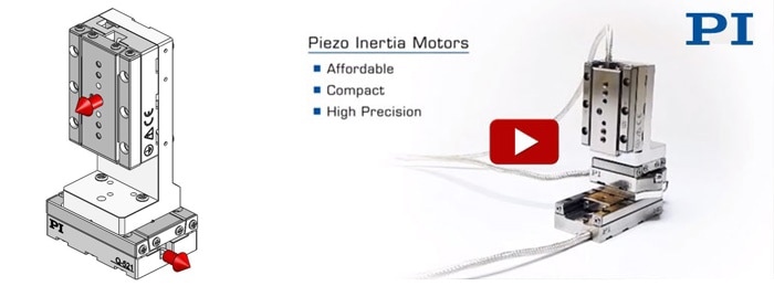
Size plays a key role in miniaturization and automation, where smaller is usually better. Conventional electromagnetic motors have certain restrictions when it comes to reducing dimensions while maintaining accuracy and high efficiency of motion along with reduced energy consumption. This gap can be addressed by Piezo ceramic inertia motors, also known as stick-slip motors. These miniature direct-drive mechanisms can be integrated in highly precise goniometer cradles, rotary stages, linear positioners and even 6-axis parallel positioning systems. Besides inertia-type motors, there are many other types of piezo motors such as high-force piezo-walk drives and high-speed ultrasonic drives.
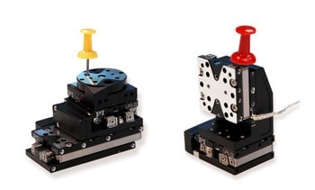
Q-motion miniature linear and rotary stages are available in single or multi-axis combinations. Their operating principle is based on the piezo inertia (stick-slip) effect.
Stick-slip motors are particularly economical and can offer nanometer precision motion, if desired. These motors offer the best force/size ratio for smallest dimensions.
Working Principle
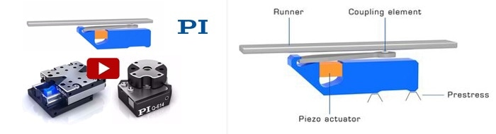
A piezoelectric ceramic actuator is preloaded against a moving runner. A drive signal with a quasi saw-tooth shape controls the actuator, which expands slowly and contracts rapidly (or in the opposite direction). During the rapid contraction, the coupling element slips along the runner, which generally remains in place, whereas during the slow expansion, the runner sticks to the coupling element and moves along.
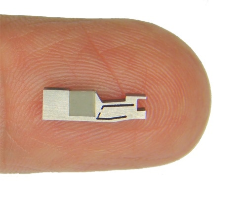
Q-motion piezo inertia motors are extremely small. They allow the design of nanometer-precision mechanisms with scaled-down dimensions that were unthinkable a few years ago – ideal for integration into miniaturized instrumentation.
There are two different versions that were developed and optimized either for moderate force, miniature size or higher force and compact size.
Tangential Inertia Drive Motor.
- To 2 N Holding Force
- Very Small Dimensions
- Simple Mechanics
Miniature Linear Stage | Miniature Rotary Table, Rotation Stage w/Piezo Motor: How it works | PI
Watch Stick-Slip Working Principle Video.
Mini-Rod Inertia Drive Motor
Mini-Rod piezo inertia motor drives are based on an actuator moving a small rod – or moving along the rod when the rod is fixed. With up to 10 N pushing/holding force, these motors are more powerful than the tangential drives. They can be incorporated into linear positioning stages and linear actuators, although the principle does not apply to rotary stages.
Stick / Slip Piezo Linear Motor Animation - Mini Motor Actuator by www.pi.ws
Mini-rod stick-slip principle.
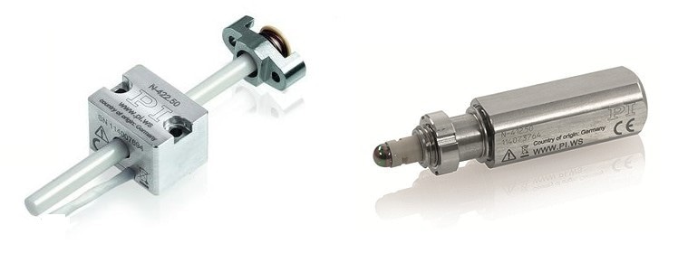
Actuators based on the Mini-Rod drive: N-422 OEM version (left) and N-412 integrated actuator (right) (Image: PI)
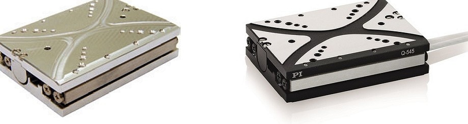
The Q-545 linear positioning stage is based on the mini-rod drive principle. Vacuum version shown left, standard version shown right, 1” travel range. Encoder resolution to 1nm is available. (Image: PI)
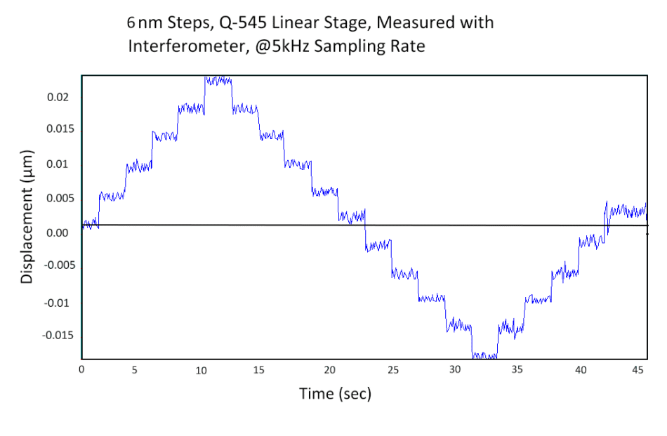
Train of 6 nm steps executed with Q-545 closed-loop stage, measured with laser interferometer at 5 kHz sampling rate. The highest encoder resolution is 1 nm. This type of resolution allows applications in high resolution microscopy. The LPS-45, a predecessor of the Q-545, was used for nanometer precise accurate positioning of the Fresnel Zone Plate along the optical axis of a compact stand-alone EUV microscope. (Image: PI)
The runner is moved in the defined direction during the stick phase, while it does not move during the slip phase. The so-called back-stepping effect causes a slight backward motion during the acceleration phase of the piezo actuator.
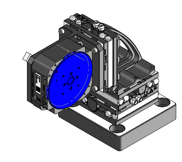
Multi-axis combination of X-Z linear stage (Q-545), with high-speed U-628 ultrasonic miniature rotary stage. (Image: PI)
Typical stick-slip cycles.
The typical feed-motion per full cycle is 300 nm to 1 µm. It depends on the actuator type and force acting on the actuator.
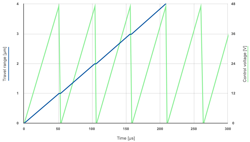
The actuator can be controlled to any position within its range with sub-nm resolution by changing the drive voltage (analog mode).
XYZ Miniature Linear Stage, Closed-Loop Piezo Motor, Inertia (Stick-Slip) | Q-Motion | www.pi.ws
(left) XY combinations mount directly without adapters. A Z-bracket is available for vertical applications.
(Right) XYZ motion with combination of Q-521 stages, 12 mm and 32 mm travel.
Self-Locking at Rest
Similar to most piezo motors, Q-Motion inertia drives are self-locking at rest. There is no position dither, no heat dissipation and no power consumption.
Velocity Control
Back-stepping Effect
Between each slip cycle and stick, a miniscule position shift known as the back-stepping effect can be observed. This effect is inseparably connected with the inertia drive principle and its relevance relies on the application.
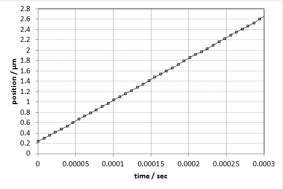
Q-522.140 with E-871.1A1 controller
• Operation Frequency 20 kHz
• Data sample rate: 133 kHz
• Time base: 0.3 milliseconds, which corresponds to 6 full stick-slip cycles
A backstepping effect is too minute to be noticed at a data sample rate of 133 kHz. As a result, PI states that the back-stepping effect does not affect the smoothness and constancy of velocity, but there are other factors that influence the velocity directly.
Constancy of Velocity at a Microscopic Level
Using the entry level E-871.1A1 motion controller, the chosen velocity is attained by adjusting the operating frequency. Adjusting the frequency means the voltage profile of a single step continues to be constant with pauses in between. More advanced velocity control is provided by the E-873 controller.
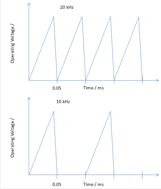
Simplified control voltage profile for different operating frequencies.
Other Piezo Motor Drives
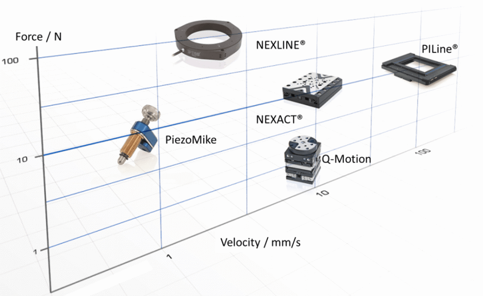
Force vs. velocity of different piezoelectric motors.
Comparison of Different Piezo Motors
| |
Stick-Slip (Q-Motion) |
Ultrasonic (PILine®) |
Low-Force PiezoWalk (Nexact®) |
High-Force PiezoWalk (Nexline®) |
| Manufacturing Cost |
+++ |
++ |
o |
- |
| Nanometer resolution available |
X |
x |
X |
X |
| Compact size |
++++ |
++ |
+ |
o |
| Velocity |
To 10 mm/s |
To >250 mm/s |
To 10 mm/s |
To 1 mm/s |
Lifetime
Lifetime is affected by environmental conditions (vacuum, humidity), duty cycle and load etc., based on wear motion ranges greater than 20 km are feasible.
Operation Recommendation
Duty Cycles
Ideal applications demand:
- Continuous operating time <10 seconds (2x back and forth across the complete travel range)
- Duty cycles below 50%
6-Axis Parallel Positioners
Besides rotary and linear positioners, linear stages can be integrated to 6-axis parallel arrangements.
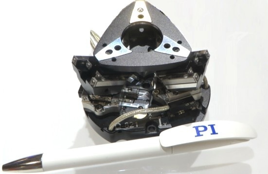
Q-821 6-axis miniature parallel positioner based on Q-521 linear stages compared to ballpen.
• 80x80x48 mm³
• 1 nm sensor resolution
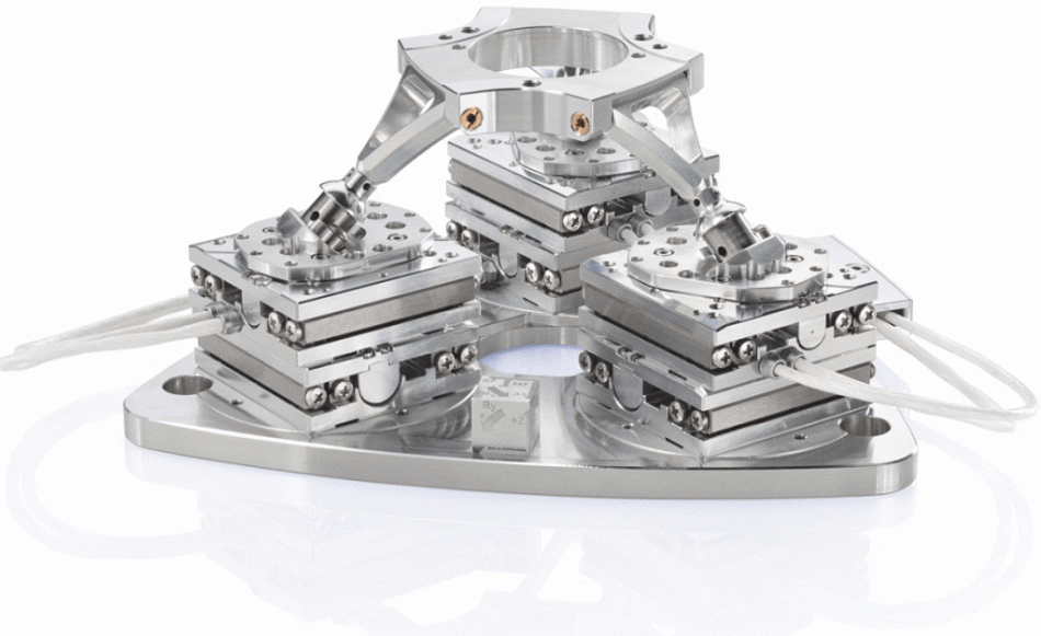
Q-845 6-axis vacuum positioner based on Q-545 linear stages.
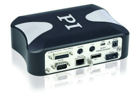
Motion Controllers
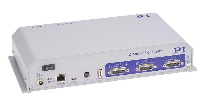
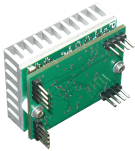
E-873 3-channel controller
The E-873 3-channel motion controller consists of:
- Interfaces: TCP/IP and USB
- ID chip support
- Digital I/O ports (TTL)
- Nonvolatile EEPROM for macros and parameters
- Data recorder
- Macro programmable for stand-alone functionality
- Broadband encoder input
- Optional digital joystick for manual operation a single channel version is available as the E-871
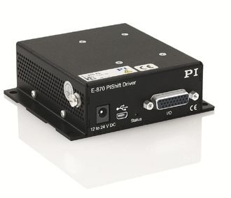
E-870 Driver
Features of the E-870 driver include:
- Host Software LabVIEW Driver Included
- With Digital USB interface
- One to Four Actuators, Serial Control (through demultiplexing)
- Ideal for OEM Applications
- For PIShift and PiezoMike Piezo Inertia Drives
E-872 OEM Driver
Features of the E-472.02 OEM and E-872.01 driver are:
- Cost Effective
- E-872.02: Micro Step Modus
- E-872.01: Full Step Modus
- Step-Direction Input Signal
E-873 Macro
The E-873 Macro programmable specifications comprise of:
- Data Recorder
- Compatible Sub-D Connectors for Q-Motion Stages
- Velocity Control
- Joystick Input for Manual Operation
- Interfaces: TCP/ IP, RS-232 , and USB
- ID Chip Support
- Digital I/ O Ports (TTL)
- Optionally Available with Metal-Sheet Housing for OEM Applications
Vacuum and Nonmagnetic Operation
High-Vacuum to 10-6 hPa
Unprepared and standard Q-Motion stages can be employed in ambient conditions and for vacuum up to 10-6 hPa. The C-815.VF vacuum feedthrough is available for vacuum operation.
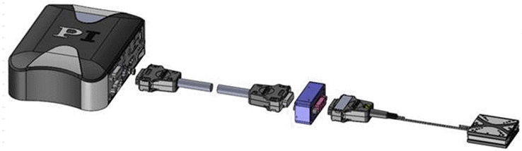
On the air side, the following cables will be available for linking the feedthrough with the E-873 controller (plus adapter cable for E-871, which is included in the delivery of the stage):
| |
Description |
| E-873.UHV1 |
Air-Side Adapter Cable, Sub-D 15, 1 m |
| C-815.VF |
Vacuum Feedthrough, Sub-D 15 |
These air-side cables are also used for the feedthrough for UHV.
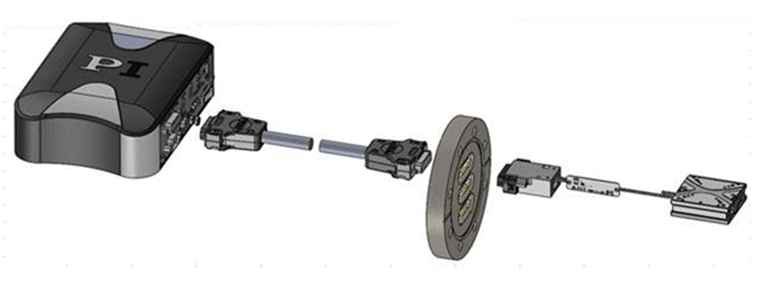
Ultrahigh Vacuum to 10-9 hPa
Ultrahigh vacuum models are also available.
| |
Description |
| C-815.VFU3 |
Vacuum Feedthrough, compatible to 10-9 hPa, 3x Sub-D 15 |
| E-873.UHV2 |
Air-Side Adapter Cable, Sub-D 15, 2 m |
Nonmagnetic Operation
At present, PI is evaluating ceramic bearings for nonmagnetic stage designs. Nonmagnetic operation is of interest in the environment of electron beam imaging such as lithography or microscopy.
Tests in High Magnetic Fields
The Karlsruhe Institute of Technology (KIT) has carried out tests in high magnetic fields of 9.4 Tesla (T). The stage (not operating) was not attracted by the magnetic field and hence was not magnetized.

This information has been sourced, reviewed and adapted from materials provided by Physik Instrumente (PI) GmbH & Co KG - Worldwide.
For more information on this source, please visit Physik Instrumente (PI) GmbH & Co KG - Worldwide.