Fringe conference can be traced to the automatic processing of fringe patterns. The term “patterns” evokes an image of flowing lines elegantly wrapped around surface contours. However, automatic processing of fringes is not restricted to this type of pattern: The fringes may be laid out along a line of sight as the time history of an object displacement, caught by a detector and processed to reveal details about how the object has moved, or more typically, where the object is relative to a reference point in space.
This article discusses distance measurement interferometry and summarizes the present state of the art of this century-old technique. Nowadays, high-performance distance measurement is vastly refined. It encompasses gravitational wave detectors to commercial systems that measure close to a nanometer while the object is swiftly changing position and orientation [1]. This brief overview will focus on applications pertinent to the photolithography industry, which is one of the most substantial customers of high-performance metrology systems today. In this context, this article looks at modern stage position monitoring and multi-point fiber sensors for high-precision absolute position monitoring.
Stage Position Monitoring
Displacement measuring interferometry or DMI for stage positioning, in its most rudimentary form, monitors the passage of fringes and calculates the change in position of an object. Latest systems obtain a relative resolution better than 1 part in 109 at data rates of several MHz along multiple measurement axes. DMI is used widely for calibration and servo control of mechanical stage motions in microlithography, precision machining, scanning electron microscopy, and e-beam mask writing.
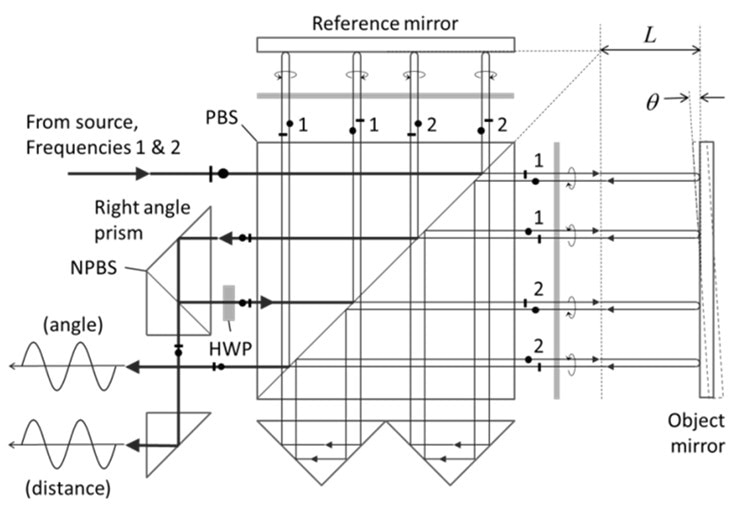
Figure 1. Modern high-stability dual-axis (distance and angle) interferometer for stage motion [2].
Figure 1 shows a DMI system for observing the linear displacement of a stage. Although some instruments use homodyne detection, most up-to-date multi-axis, high-precision interferometer systems are heterodyne. The modulated laser head presents two collinear collimated beams of orthogonal polarizations and slightly different frequencies so as to produce a heterodyne beat signal when combined [3, 4]. The interferometer optics detach the polarizations and direct them to the object and reference mirrors in a double-pass configuration such that the beams recombine at the detector without tilt fringes, independent of small angle variations in the stage mirror orientation. The interferometer in Figure 1 monitors both displacement and one angle [5]. Monolithic interferometers compare the relative two-angle orientation, straightness of motion and position of stage components with respect to a fixed metrology frame or subsystems [6]. Specialized interferometers observe changes in the environment [7] as well as the overall stability of the structure that carries the stage and photolithography projection optics.
High-speed electronics decode the heterodyne beat-signal phase and account for stage position. Phase detection includes sliding-window Fourier methods with embedded data age and cyclic error correction [8-11]. General performance characteristics consist of sub-nm uncertainty for stage metrology at velocities of up to 2 m/s. The stage motion is fast enough that the electronics must take into account the amount of time that it takes for the interference information traveling at the speed of light to reach the data processing unit. Detailed uncertainty analyses are compulsory when controlling for photolithography overlay budgets and other demanding applications [12, 13]. Stage metrology solutions calibrate dozens of orientation and position parameters in production photolithography systems, as illustrated in Figure 2.
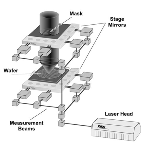
Figure 2. Photolithography stage measured by heterodyne interferometry. Modern systems have multiple measurement axes and include optical encoders such as the subsystem shown in Fig. 3.
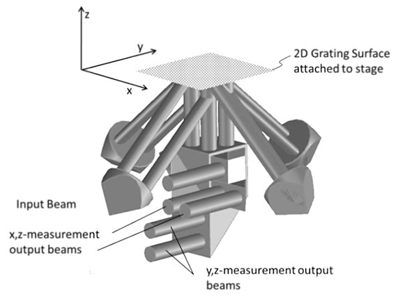
Figure 3. Optical heterodyne encoder based on DMI components and a for monitoring the in-plane and out-of-plane motion of a 2D diffraction grating [14].
Metrology systems are based on the fundamental principles of highly-refined fringe counting. However, they have become more complex with the ongoing reduction in feature size of semiconductor electronics. Of late, photolithography systems have inched towards optical encoders as a means of beating the problem of air turbulence [14-18]. Here the “fringes” are physically imprinted on 2D grid and monitored by new optical configurations such as the three-axis heterodyne encoder shown in Figure 3.
Fiber Sensor for Ultra-Precision Positioning
Fiber-based, high-accuracy interferometric distance sensors depict the latest generation of devices that couple installation flexibility with compact size. Interferometric sensors eradicate the range-resolution trade-off feature of capacitance and intensity-based fiber sensors. The latest sensors allow high-resolution (pm) measurements over macroscopic ranges (mm). This category of sensors focuses on metrology applications for the measurement of both absolute distance and displacement without phase ambiguity over short ranges, lending the ability to organize an absolute home position in a sense akin to capacitance gauges.
Several requirements encourage the design of such systems for position monitoring in state-of-the-art photolithography systems including zero heat dissipation in the sensing elements, sub-nm drift over extended periods (hours), flexibility in the location of sensors, remarkably high reliability (many years with negligible chance of failure) to prevent system downtime, a clearly defined (and accessible) measurement datum, compact sensor size, and insensitivity to electromagnetic interference (EMI).
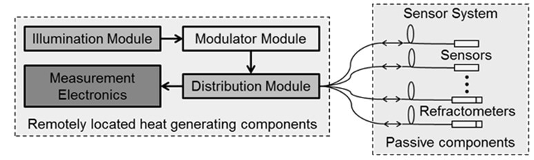
Figure 4. Fiber interferometer system architecture.
Figure 4 shows the modular architecture of the system which segregates the portions that may require replacement/maintenance from the passive high-reliability sensors embedded within restricted access areas [19, 20]. This architecture restricts the heat generating components to locations outside the thermally controlled envelope. A spectrally broad light source whose mean wavelength can be set at three discrete values provides illumination. While only one wavelength is required for displacement measurement, the multiple wavelengths and the method of exact fractions enable the establishment of the absolute position of the target relative to the measurement datum [21]. The modulator module transmits a phase modulation to the incoming illumination to enable the recovery of phase information in the measurement electronics. The optical distribution module that follows directs the modulated illumination to a multiplicity of sensors in the sensor subsystem. It also restores the reflected light from the reference surfaces of the sensors and aims and guides it to the measurement electronics. Sensors can be set up to sense position or refractive index of the medium of operation. The measurement electronics change the optical signals into electrical signals and eventually produce an index or position readout.
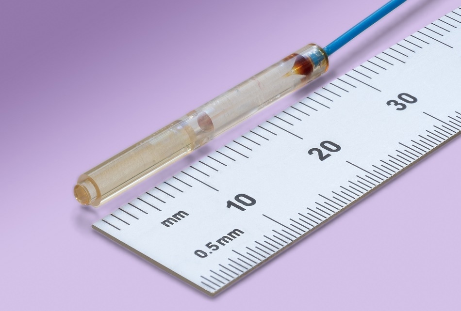
Figure 5. Image of the sensor
The exposed surface of the GRIN (gradient index) lens forms one side of the interferometer cavity and acts as the datum for the measurement. The system is designed for high resolution, high bandwidth measurements for over 60 measurement channels. Table 1 outlines the performance characteristics of the system. Especially noteworthy are the unusually low noise of 0.014 nm-Hz-1/2 and the drift specification of 1 nm/day.
Table 1. Performance characteristics of the fiber interferometer
| Parameter |
Value |
| Number of channels |
64 |
| Measurement range |
1.2 mm |
| Standoff |
3.5 mm |
| Repeatability (1 kHz) |
0.5 nm |
| Bandwidth |
100 kHz |
| Noise (3σ) |
0.014 nm-Hz-1/2 |
| Drift |
1 nm/day |
| Linearity |
2 nm |
Acknowledgments
This outline depicts the work of the engineers and scientists in ZYGO’s Precision Positioning and R&D groups, whose skill and dedication are gratefully acknowledged.
References
- Badami, V, de Groot, P (2013) Displacement measuring interferometry. In Handbook of optical dimensional metrology, Harding, K. G., ed., Taylor & Francis, Boca Raton: 157-238
- Zanoni, C (1989) Differential interferometer arrangements for distance and angle measurements: Principles, advantages and applications. VDI-Berichte 749:93–106
- Sommargren, G E, Schaham, M (1987) Heterodyne interferometer system. Patent US 4,688,940
- Steinmetz, C R (1988) Displacement measurement repeatability in tens of nanometers with laser interferometry. SPIE Proceedings 921:406-420
- Sommargren, G E (1989) Linear/angular displacement interferometer for wafer stage metrology. Optical/Laser Microfithography II 1088:268-272
- Evans, C, et al. (2005) Metrology and calibration of a long travel stage. CIRP Annals - Manufacturing Technology 54:495-498
- Sommargren, G E (1988) Apparatus for the measurement of the refractive index of a gas. Patent US 4,733,967
- Demarest, F C (1998) High-resolution, high-speed, low data age uncertainty, heterodyne displacement measuring interferometer electronics. Measurement Science and Technology 9:1024-1030
- Hill, H A (2009) Apparatus and methods for reducing non-cyclic non-linear errors in interferometry. Patent US 7,528,962
- de Groot, P (1999) Jones matrix analysis of high-precision displacement measuring interferometers. Proc. 2nd Topical Meeting on Optoelectronic Distance Measurement and Applications (ODIMAP II) 9-14
- Hill, H A (2001) Systems and methods for quantifying nonlinearities in interferometry systems. Patent US 6,252,668
- Holmes, M L, Evans, C J (2004) Displacement measuring interferometry measurement uncertainty. ASPE Topical Meeting on Uncertainty Analysis in Measurement and Design 33:89-94
- Mielke, S L, Demarest, F C (2008) Displacement measurement interferometer error correction techniques. Proc. of the ASPE Topical Meeting on Precision Mechanical Design and Mechatronics for Sub-50nm Semiconductor Equipment 43:113-116
- Deck, L L, et al. (2012) Interferometric encoder systems. US Patent 8,300,233
- de Groot, P, Schroeder, M (2012) Interferometric heterodyne optical encoder system. US Patent 2012/0194824 A1
- Kimura, A, et al. (2010) Design and construction of a two-degree-of-freedom linear encoder for nanometric measurement of stage position and straightness. Precision Engineering 34:145-155
- Heilmann, R K, et al. (2004) Dimensional metrology for nanometre-scale science and engineering: Towards sub-nanometre accurate encoders. Nanotechnology 15:S504-S511
- de Groot, P, Liesener, J (2013) Double pass interferometric encoder system. US Patent 2013/0114061
- Deck, L L (2009) High-performance multi-channel fiber-based absolute distance measuring interferometer system. Instrumentation, Metrology, and Standards for Nanomanufacturing III 7405:74050E-1 - 74050E-9
- de Groot, P, et al. (2010) Interferometer system for monitoring an object. US Patent 7,826,064
- Lewis, A J (1993) Absolute length measurement using multiple-wavelength phase-stepping interferometry. Ph.D. Thesis, Department of Physics, Applied Optics Group, University of London

This information has been sourced, reviewed and adapted from materials provided by Zygo Corporation.
For more information on this source, please visit Zygo Corporation.