
Precision automation systems and instrumentation equipment manufacturers depend on motion components in applications from micro-mechanical assembly to optical scanning. PI offers a wide range of standard and custom motion positioning solutions to support these applications. Great adaptability and high-performance at a reasonable cost is possible due to the combination of in-house-developed and off-the-shelf mechanical and electronic components, including actuators, position sensors, guiding systems, and motion controllers.
While gearbox / screw-driven positioning elements offer benefits to vertical and high force applications, direct-drive electrodynamic motors provide improved zero-wear, higher speed, and friction-free transmission devices that are favored in positioning and scanning systems that necessitate high dynamics and dependable repeatability over millions of cycles.
Further to designing piezo-ceramic direct-drive linear and rotary motors, engineers at PI have well-established history of developing customized motion systems with electrodynamic motors, specifically for applications requiring high-precision and/or high-dynamics. The primary intention is to achieve distinct performance targets that cannot be attained using standard off-the-shelf products available on the market. This following link is a paper dating back to 2000 linked to a novel momentum compensated high-speed voice coil linear scanner; other examples include multi-axis Maglev systems, high-speed hexapods, and compact voice coil motors with force and position control.
Throughout this piece will be the examination of the functional principle and properties of 3-phase linear, voice coil, and torque motors. Thereby, examples will be provided on how performance characteristics of the various motor types can be molded to the specific requirements of the positioning solution through an individual design, e.g., to achieve a compact design or high force density.
2. Electro-Magnetic Direct Drives – How do they Work?
In contrast to common motor/screw-drive technologies, direct drives provide benefits, specifically with regards to wear and dynamics. By minimizing the mechanical components, as well as the removal of friction and backlash, there is the resulting increase of improved accuracy and longer service life. 3-phase linear, Voice coil, and torque motors can be classified as electrodynamic motors, but their operating principles diverge.
2.1. Voice Coil Motors
Voice coil motors (their name comes from their use in loudspeakers) utilize the Lorentz force, which is when the generated force is equivalent to the magnetic field strength and the current of the current-carrying conductors. The resulting force acts bi-directionally, which is contingent on the direction of the current.
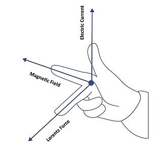
The Right-Hand-Rule explains the direction of the force relative to the direction of the current and the magnetic field
How Does a 6D MagLev Stage provide Nanometer Precision Motion? Magnetic Levitation | www.pi.ws
Video: Maglev 6-DOF positioning system with PIMag® electromagnetic drives. A magnetic field levitates the platform and guides it actively.
Cylindrical voice coils are manufactured in accordance with the plunger coil principle, i.e., the winding body sits in a field assembly as indicated in Fig. 1. This means that the winding body (“moving coil”) or the pot (“moving magnet”) are disturbed when energized. Hollow shaft voice coils can be deployed in applications such as a being easily integrated as a feedthrough for a linear guiding system.
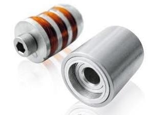
Figure 1. Miniaturized cylindrical PIMag® voice coil motor for use in medical endoscopes
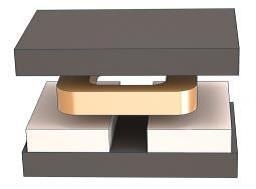
Figure 2. Voice coil motor with a flat design
How Does a Voice Coil Motor Work - Applications in Linear Actuators and Linear Stages. By www.pi.ws
Video: Explanation of the Voice Coil Linear Motor Operating Principle
When precision scanning motion with high dynamics and relatively high forces is necessary voice coil motors can be utilized for travel ranges of 1 inch and below. For example, the V-522, V-524, and V-528 linear stage series (as shown in Figure 3) have their foundations in voice coil motors from PI.
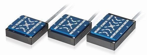
Figure 3. Compact linear stage series with flat-design voice coil motors: models V-522, V-524, and V-528 (from left to right)
XY Linear Stage, Voice Coil Linear Motor for Scanning, Fast, Precision, V-528 Multi-Axis, XY-Table
Video: V-528 stage in motion
Customization and optimization for voice coil motors for different parameters are enabled by simulation tools. The requisite parameters, in this case motor constant, signifies the ratio of force to power loss, or the efficiency of the motor regarding transforming electrical into kinetic energy. The higher the motor constant, the less heat is produced when a specific force is produced. The motor constant is also temperature-dependent; thus, with an increase in temperature comes an increase in the winding resistance leading to increased power loss.
As a consequence, PI has developed and produced cylindrical motors, as shown in Figure 4, to maximize the motor constant.
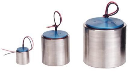
Figure 4. PIMag® cylindrical voice coil motors; optimized size and motor constants
6-DOF Motion Platform: High Speed & Dynamics; Shaker Hexapod Motion Simulator, www.pi.ws
Video: Voice coil-driven hexapod 6-DOF motion platform for highly dynamic multi-axis motion simulation
They are characterized by a maximized ratio of motor constant to installation space and can be manufactured in various sizes. Cylindrical motors can be used in fast-focusing applications, for moving a measuring head in a metrology system vertically. In combination with a flexure guiding system, especially compact units can be built.
Table 1 shows the performance characteristics of three examples in different sizes.
Table 1. Examples of custom PI cylindrical voice coil motors for OEM positioning systems.
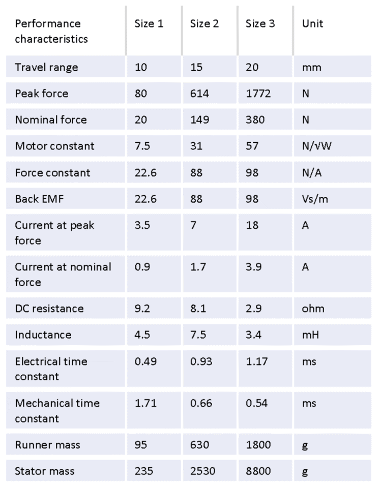
Figure 5 shows the force-displacement dependency. The variation is due to the variable distance between the coils, which move in relation to the permanent magnets along the travel range. This can be seen in Figure 5.
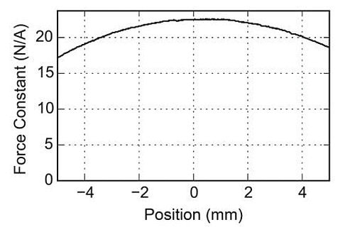
Figure 5. Force-displacement diagram of a cylindrical PIMag® voice coil linear motor
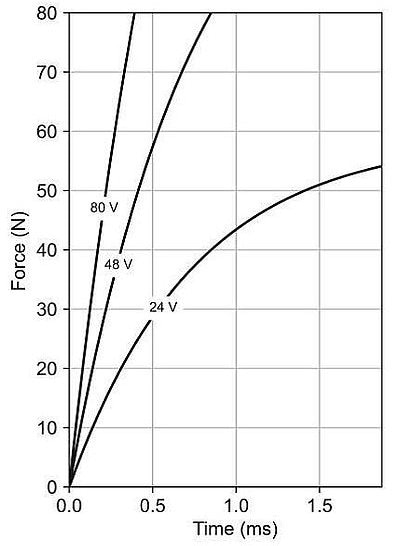
Figure 6. Force-time diagram of a cylindrical custom voice coil motor
To refine the force / rise-time relationship, the voltage can be increased as shown in Figure 6. Therefore, with a surge in the voltage, the current and force can rise rapidly, leading to better acceleration (jerk) and dynamics.
2.2. 3-Phase Linear Motors
A traditional 3-phase linear motor is fundamentally a sequence of at least three (or a multiple of three) voice coil motors which are controlled, i.e. commutated, by a position-dependent, fixed pattern. Illustrated in figure 7 is a motor composed of three coils in a U-shaped magnetic track.

Figure 7. Design of a linear motor showing the magnetic track and three current-carrying coils.
Linear Motors - How Does a 3-Phase Motor work in a Linear Motor Slide | Direct Drive Motors
Video: Animation of 3 –phase linear motor principle
Custom sheathed linear motors available from PI are suitable for vacuum applications. The effect is improved heat dissipation, enabling higher nominal forces. Additionally, the sealing compound guarantees that the motor is protected from external damage, e.g. during assembly.
For applications that specifically require high velocities or fast current rise times, PI can design motors for operating voltages up to higher values (600 VDC). Thus, linear motors gain advantage from the same effect that was already explained for voice coil motors. High-voltage servo amplifiers, as standard in industrial applications, are available to drive these motors.
Halbach Arrays
The length of magnetic tracks for OEM positioning systems can be customized by PI - single-sided or U-shaped magnetic tracks are offered. U-shaped magnetic tracks reach higher magnetic field strengths and higher forces than single-sided magnetic tracks. By arranging the magnets in a Halbach array, the magnetic field strength can be enhanced by around 10% compared to a North / South Pole arrangement.
Furthermore, the iron counter plate can be excluded in a Halbach array, which means that these magnetic tracks are notably lighter (Fig 8). The benefit of using a Halbach array also applies to single-sided magnetic tracks. In this case, the use of Halbach arrays circumvents the generation of high stray fields on the reverse of the single-sided magnetic track. PI can offer carbon supports for applications that necessitate ultra-light magnetic tracks.
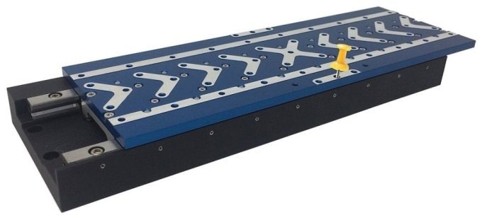
Figure 8. V-508 linear stages are driven by PI's proprietary PImag® Halbach array linear motors allowing for a particularly flat, lightweight design.
XY-Stage - Direct Drive Linear Stage w/Linear Motor, fast Scanning & Alignment, V-508 Linear Stage
Video: V-508 XY linear stage in fast photonics scanning and alignment application with ACS motion controller
2.2.1. Iron-Core Linear Motors
Applications that require high forces and accelerations with restricted installation space call for Iron-core linear motors. The iron promotes high thermal stability and maximizes the magnetic forces. To reduce eddy current losses, the iron is laminated and it is manufactured largely from stacked and insulated transformer plates.
The downfall of iron-core motors is the resulting attraction force that occurs between the iron and the magnets arranged on the reverse side. This increases further still if a steel linear guide is in use. ‘Cogging’ is also a concern since the displacement force varies over the travel range – while this can be significantly reduced using special geometries, it cannot be completely removed from the process but advanced control algorithms can neutralize it for most applications. An example of an iron-core linear motor is illustrated in Figure 9.
Ironless and iron-core linear motors are available. For example, motors of both types are used in the V-508 linear stage series. An example of a linear stage of this series is shown in Figure 8.
The sealed motor shown in Figure 10 is an example of a proprietary linear iron-core motor developed by PI.
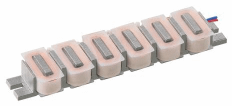
Figure 9. Example design of an iron-core linear motor without a magnetic track
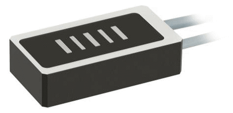
Figure 10. PIMag® linear motor with laminated magnetic steel and epoxy-resin sealing
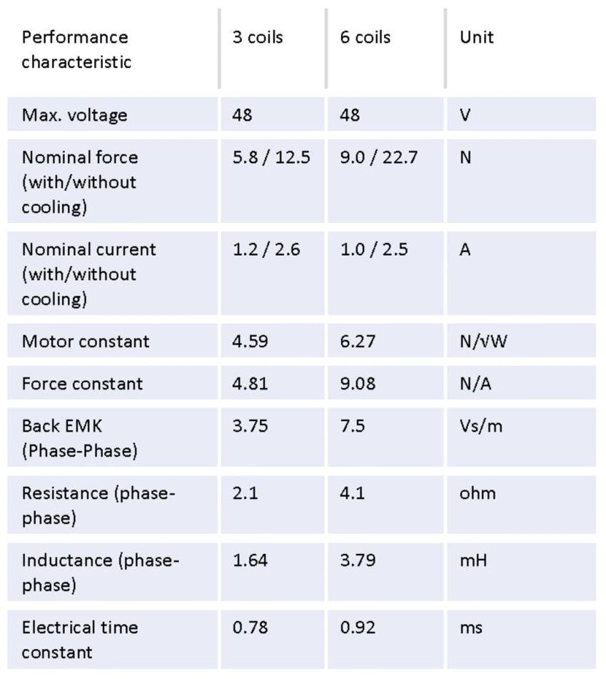
The iron-core linear motors are available with three or six coils (see performance characteristics in Table 2).
Table 2. Examples of sealed linear motors with three and six coils
To secure a persistent and constant force, the linear motors are designed to achieve a specified maximum speed. This can be seen clearly in Figure 11 with the example of an iron-core linear motor. In conjunction with other parameters, the maximum speed is contingent on the motor voltage supplied.
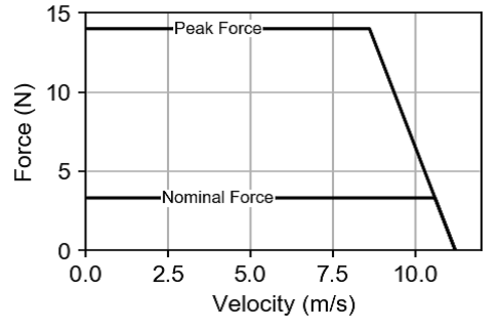
Figure 11. Force-speed diagram of an iron-core linear motor
2.2.2. Ironless Linear Motors
Due to being unaffected by cogging, ironless linear motors are ideal for positioning tasks with the highest demands on accuracy, linearity, and speed stability. They are also perfect for installation into limited spaces thanks to their uniquely flat design. By increasing the number or dimension of the motor coils, power and dynamics requirements can be met.
Generally, ironless motors operate at lower nominal and peak forces than iron-core motors. This is due to the shortage of thermally conductive metals in the design and the resulting limited heat dissipation from the coils. However, protection against overload in the motors is achieved using additional temperature sensors. An example of an ironless linear motor is displayed in Figure 12.
The flat motor with a U-shaped magnetic track, as illustrated in Figure 13, is an example of a proprietary ironless linear motor developed by PI.
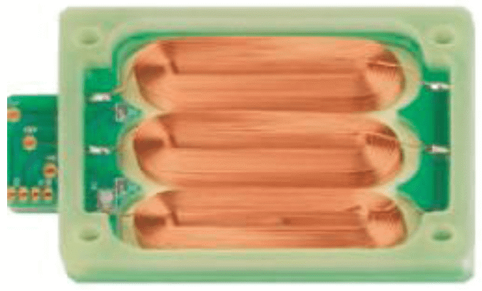
Figure 12. Example design of a PIMag® ironless linear motor without a magnetic track
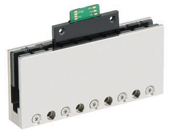
Figure 13. Flat PIMag® linear motor with three coils and u-shaped magnetic track
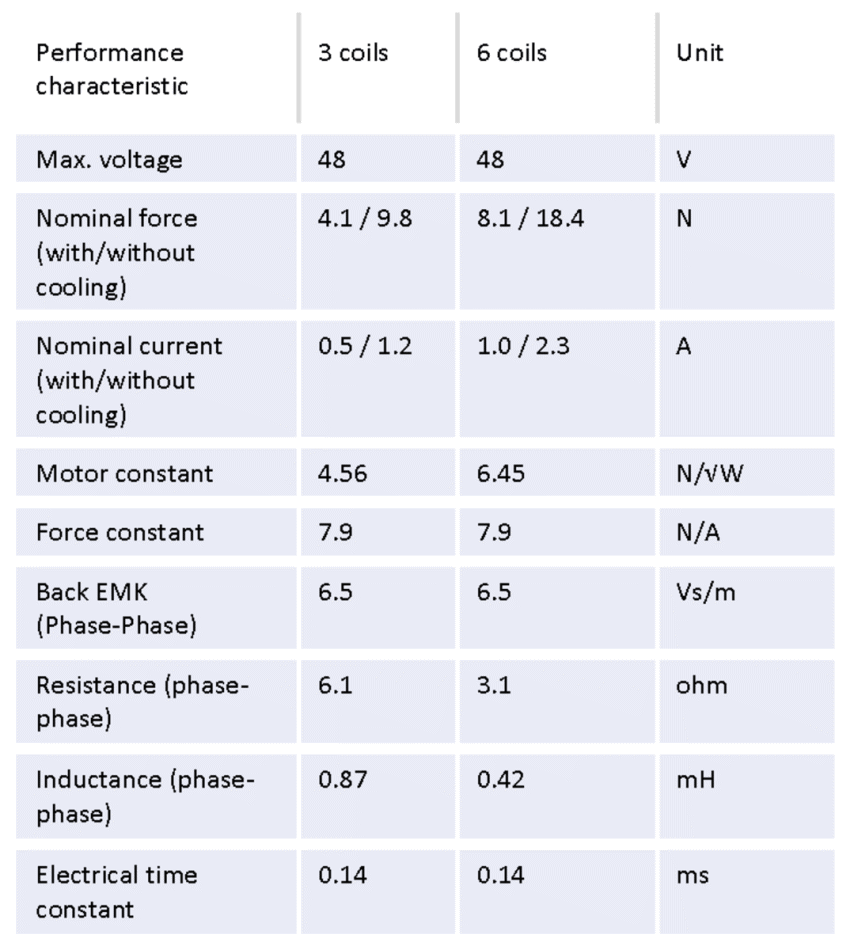
Ironless motors are offered with three or six coils. The performance properties are shown in the two examples in Table 3.
Table 3. Low profile custom motors with three or six coils
2.3. Torque Motors
Torque motors are typically deployed in rotation stages for positioning and automation applications that require great accuracy. Unlike worm-gear driven stages, rotation stages based on direct drive torque motors display zero play and backlash.
Combining these with frictionless air bearings, they supply a service life that is in effect unlimited (Figure 14a). A torque motor is essentially a radially designed 3-phase linear motor. Alternatively, designs can allow for the rotor to be characterized as a rolled-up, single-sided magnetic track, while the stator houses the coils which are embedded in an iron matrix. An illustration of a typical custom torque motor developed by PI can be seen in Figure 14b.
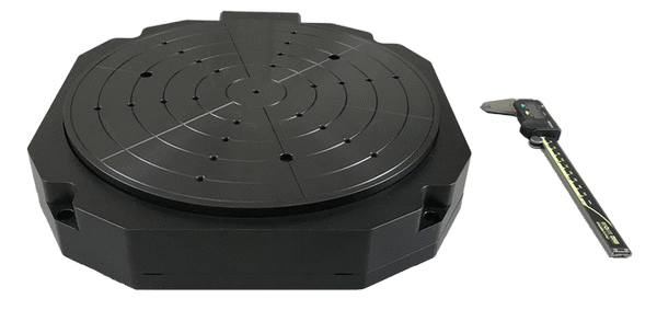
Figure 14a. A-637 Low profile air bearing rotary stage driven by torque motor
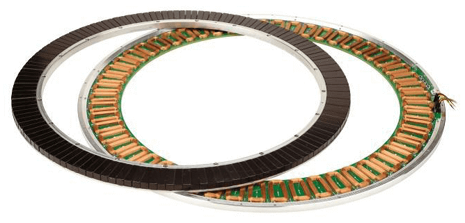
Figure 14b. Ultra-low profile custom PIMag® torque motor with large aperture
The torque scales quadratically with the diameter while the magnet length scales linearly. Larger diameters offer much more torque and enable larger apertures that can be utilized for the passage of cables or laser beams.
Torque motors are mostly used for direct drive rotation stages throughout precision positioning applications. Such a rotation stage is shown in Figure 15a, stacked on a hexapod. This example displays an ultra-flat, highly dynamic, and stable torque motor rotation stage with an exceptionally large aperture. The common aperture of the rotation stage and the hexapod can be used, e.g. as feedthrough.
Direct-drive rotary stages mounted on top of 6-axis hexapod stages to add 360-degree rotation capability for alignment and automation applications that require great accuracy. Fig 15a and 15b clearly illustrate examples of custom 7-axis positioning systems.
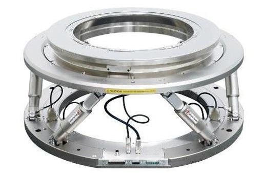
Figure 15a. “6+1 Axis” precision motion system: Low profile PIMag® torque motor rotation stage adds 360° rotation capability to large aperture 6-DOF hexapod multi-axis positioning system.
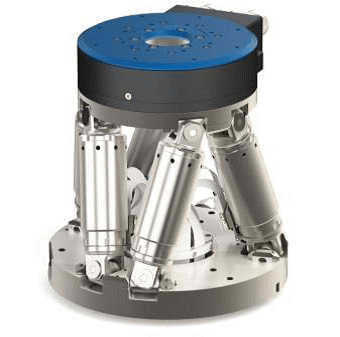
Figure 15b. V-610 compact PIMag® torque motor rotary stage stacked on an H-811 hexapod to extend the rotation range for use in highly automated production systems
Multi-Axis Stage: 6-Axis Hexapod + XY Stage Range Extender for Multi-Axis Motion and Automation
Video: Compact hexapod with linear motor stage XY range extender
3. Summary
PI offers its customers competitive and ambitious solutions with performance characteristics that are adapted to the specific requirements of the application. This is down to the in-house expertise and guidance necessary to developing proprietary motors with the core technologies needed for a complete positioning solution, such as sensors, guides, and motion controllers. Figure 17, for example, demonstrates an application that combines a variety of motor types.
The multi-axis setup for autofocus applications shown consists of an X and a Z axis. The X axis, for example, clasps a workpiece that is to be machined on a V-508 linear stage. Supplementary to the ordinarily used piezoceramic drives, the voice coil Z axis allows for long travel ranges up to several millimeters. This is vital, for laser material processing as well as having significant impact elsewhere. Travel ranges of 1 to 7 mm are usually required for multiphoton fluorescence microscopy and deep tissue microscopy. Moreover, voice coils provide greater maximum speeds which can, for example, be used to improve throughput when using breakthrough methods such as “scanning-on-the-fly mode” in digital slide scanning processes.
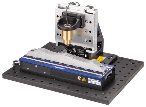
Figure 17. Fast autofocus demonstrator with voice coil Z axis stage and 3-phase linear motor on the X axis
Thanks to PI's vertical range of manufacturing and technological range, PI is the perfect partner even when customers only need just one single component of a positioning solution.

This information has been sourced, reviewed and adapted from materials provided by PI (Physik Instrumente) LP.
For more information on this source, please visit PI (Physik Instrumente) LP.