Many electron microscopists use remote plasma cleaning—a well-established technique—to remove hydrocarbon (HC) contamination and get perfect images from their instruments.1
The oxygen radicals produced in the plasma generate CO, CO2, and H2O by reacting with carbon compounds, and these generated byproducts are eliminated from the instrument.
As per quantum chemistry rules relating to energy loss, such oxygen atoms do not react with diatomic molecules in two-body collisions; however, they require a three-body collision to dynamically eliminate excessive energy.
In the case of SEM vacuum chambers, oxygen radicals can react on various metal surfaces, including the chamber walls, where they can be lost or recombine at pressure-based recombination rates.
Using experimentally-contaminated quartz crystal microbalances (QCM), XEI Scientific has performed several studies2–4 to find out the cleaning rates and eventually demonstrated highly effective removal of hydrocarbons (refer to Figure 1).
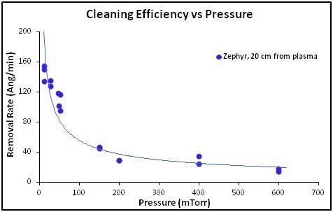
Figure 1. Hydrocarbon removal rate versus gas pressure at 20 W of RF power delivered to the plasma. Pressures above 100 mTorr were achieved using only a roughing pump, while a turbo molecular pump was used for pressures <100 mTorr to run in the Turbo Plasma cleaning mode. Image Credit: Evactron (XEI Scientific)
Fast decontamination rates were captured in SEMs and FIBs that were delivered with turbo molecular pumps.5,6 At lower pressures, the reduced gas density and the longer mean free path led to higher cleaning effectiveness since fewer radicals were lost by collision (refer to Figure 1).
Lower pressures and longer mean free paths lead to the formation of a flowing afterglow outside of the remote plasma radical source, in which metastable species decay, emitting visible and ultraviolet photons. This afterglow light subsequently forms in the entire volume of the SEM and lights up all the surfaces.
If air is utilized as the plasma source, a nitrogen afterglow with a separate violet color will be observed from the decay of N2+ metastable species.
A range of neutral nitrogen metastable species create UV lines at shorter wavelengths, and this provides energy to chamber surfaces to trigger the disassociation and desorption of hydrocarbons, causing oxidation by the reactive oxygen radicals.
This process speeds up the plasma cleaning activity and the following pump down. And this process has also been examined with a residual gas analyzer (RGA), a spectrometer, and quartz crystal monitors (QCMs) to demonstrate virtually the complete removal of hydrocarbon contaminants from the chamber.
A new study measured the positioning of the plasma radial source and the impacts of chamber geometry on cleaning efficiency. This analysis also demonstrated the benefit of plasma cleaning to create hydrocarbon-free sample surfaces for optimal data collection in TKD/EBSD experiments.
Theory
Oxygen radicals are developed in remote or downstream plasma cleaning and these radicals enter the vacuum chamber in the form of excited plasma. Air serves as the process gas in Evactron® Plasma Cleaning. At low pressures, a flowing UV afterglow is seen from the excited metastable nitrogen molecules with a usual violet/pink color.
The concentration of neutral radicals in the plasma flowing UV afterglow is a function of the rate of loss in the neutral afterglow and the rate of production in the plasma. The production rate (Rp) is a function of the total pressure P, fractional pressure of O2 (PO2), power W, reaction rate constant k and device constant D.
Rp = F(PO2, P, W, D, k)
- The loss rate RL is a function of the recombination rate by collisions (Rc) in the gas stage and a function of the loss rate caused by collisions on the wall
- The number of generated radicals can be assumed to be the same at all pressures
- The collision rate is a function of the rate of three-body collisions that follow the overall pressure cubed and the rate of loss to the wall, which follows the ratio of wall and the overall pressure to the plasma volume
- Since the collision rate in the UV afterglow is highly sensitive to pressure, P/PO2 will increase when the pressure drops until a crossover point is realized when the rate of radical production reduces below the RL, and PO2 starts to decrease with pressure
- The length and diameter of the radical conductance regulate the rate of radicals reaching the chamber
- The rate of loss to the wall can be regulated by selecting an ideal location for the PRS on the vacuum chamber
As per the theory, the shorter tube offers higher cleaning rates and better conductance.
Chamber Specifics/Geometry
In general, the commercial remote plasma cleaners available for SEMs connect the plasma radical source (PRS) for cleaning on an accessible port provided on the SEM chamber via KF40 or almost the same-sized flanges.
To achieve a short connection to the SEM chamber, the remote plasma cleaner should be small and fit among other GIS, probes, detectors and accessories linked to a SEM chamber. For example, if the remote plasma cleaner occupies more angular space, the functionality or cleaning rate of other devices may be lost.
The system should also be adaptable with turbomolecular pump vacuum systems of field-emission SEMs.
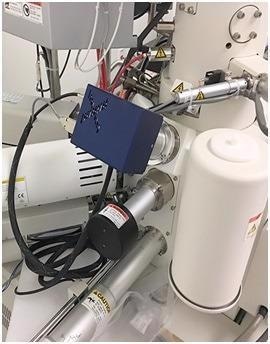
Figure 2. The compact Evactron E50 model fits among a forest of accessories on a crowded SEM chamber. Image Credit: Evactron (XEI Scientific)
To deal with this issue, XEI Scientific has designed the compact Evactron E50 system to plasma clean at turbo molecular pressures. A fixed input flow rate used by the PRS is preset to prevent the need for a modifiable vacuum gauge or flow valve.
Since SEM users only prefer a good cleaning rate and are not performing plasma analyses, there is no need to adjust the vacuum gauge and flow rate.
The Evactron system is also compact because it integrates an energy-efficient RF Hollow Cathode (RFHC) plasma generator. This design creates high-density plasma without the generation of additional heat associated with an inductively coupled plasma (ICP) coil.
ICP uses higher power compared to Evactron RFHC, analogous to the power ratings of incandescent lamps versus compact fluorescent lamps. Rather than creating radicals, an ICP tends to waste power by heating a coil with an RF current. By contrast, the Evactron plasma cleaners are smaller, operate cool and use dual-action UV and plasma cleaning to provide the 'Fastest Way to Pristine™.'
Materials and Methods
Tests were carried out to demonstrate the effect of distance and geometry on the loss of radicals by recombination on tube walls. In these tests, QCMs were used to quantify the level of oxygen radicals by assessing the removal rate of a hydrocarbon film.
- An Evactron 25Z PRS was used to create oxygen radicals at 20 W RF power
- The length of the stainless-steel radical delivery tube was varied between 9 and 32 cm between the Evactron Zephyr™ PRS and the port on the chamber wall
- The input flow rate of air was set at 20 sccm
- QCMs were left in a fixed position within the 20-cm diameter chamber
- The PRS is moved away from the port by adding 40-mm diameter KF 40 connectors of different lengths between the port and the chamber
- A turbopump was used at dual speeds to vary high-vacuum pressure, and pumping was carried out solely by the roughing pump at low vacuum
Figure 3 shows the experimental setup with an Evactron Zephyr PRS. Table 1 shows the results for different lengths and geometry of the connector tube.
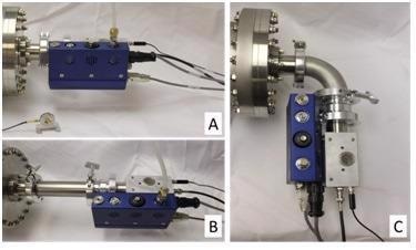
Figure 3. Experimental set-up to show the effects of distance and radical loss on cleaning efficiency of an Evactron Zephyr PRS. (A) 9 cm straight, (B) 32 cm straight, and (C) 22 cm curved connector. Image Credit: Evactron (XEI Scientific)
Table 1. Turbo Plasma cleaning rates with different connector lengths and shapes. Cleaning efficiency measured at 20 W with Zephyr system on a 22-L test chamber. Source: Evactron (XEI Scientific)
| . |
. |
. |
. |
. |
. |
| Connector Type |
Straight |
Straight |
Straight |
Curved |
Straight |
PRS distance from
main chamber volume (cm) |
9 |
13 |
22 |
22 |
32 |
Cleaning Rates at
20 Watts (Ang/min)* |
324 |
269 |
157 |
142 |
108 |
*- Pressure during plasma operation: 2.5E-2 Torr (T-Pump cleaning mode with TMP at low speed)
Results and Discussion
Cleaning Rates Versus Distance of PRS from Main Chamber
Etch rate reduces and radical recombination increases with distance, as illustrated in Table 1. As the distance between the main chamber volume and the PRS increases, the cleaning and radical concentration rates reduce because of collisions with gas species and tube walls.
Oxygen radicals are lost on chamber walls at pressure-based recombination rates in SEM vacuum chambers.
If attempts are made to link an extension pipe to move the PRS further from the chamber because of other accessories and the site of available ports, the level of oxygen radicals and the rate of cleaning will reduce based on the geometry and length of the tube, as seen in the comparison between straight versus curved connectors.
Flowing UV Afterglow Cleaning
Since 2010, SEMs delivered with TMPs have become the standard laboratory equipment and, at lower pressures, the plasma cleaning could be carried out. The effective cleaning distance and the cleaning efficiency increased due to a longer mean free path at lower pressures.
At low pressures below 40 mTorr, N2 flowing UV afterglow from the plasma was observed.
The flowing UV afterglow is also neutral and is predominantly free of electrons and ions. It includes nitrogen metastable species (refer to Figure 4) that decay to create the UV afterglow and oxygen radicals that oxidize the hydrocarbons.
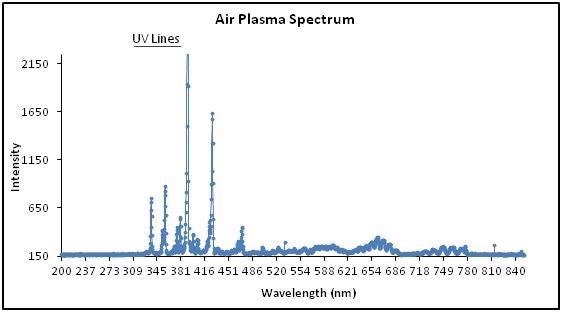
Figure 4. A spectrum of Evactron air plasma demonstrating characteristic UV wavelengths. Image Credit: Evactron (XEI Scientific)
The distinct violet peak at 384 nm is caused by the N2+ ion. Below this peak are N2 metastables—that is, the shorter UV wavelength peaks that provide energy to surface molecules.
By desorbing water vapor and by activating hydrocarbons for the oxidation of oxygen radicals, afterglow UV speeds up the cleaning procedure. Since the flowing UV afterglow fills the whole chamber volume, surfaces are lighted up from all angles.
Complete Hydrocarbon Cleaning Confirmed by RGA Spectra
Spectra were acquired using an Ocean spectrometer with quartz lens through a quartz window into the vacuum chamber (refer to Figure 5A) contaminated with a familiar thickness of pump oil.
The comparison of spectra both before (refer to Figure 5A) and after (refer to Figure 5B) 5 minutes of cleaning demonstrates the removal of all hydrocarbon peaks from the spectrum. The results obtained vary with numerous hydrocarbon contaminants.
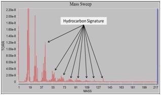
Figure 5A. HC signature before cleaning. Image Credit: Evactron (XEI Scientific)
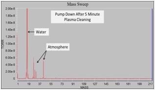
Figure 5B. HC removed after 5-minute cleaning. Image Credit: Evactron (XEI Scientific)
An Example of Why Clean Samples are Critical: EBSD/TKD Data
Transmission Kikuchi diffraction techniques meant for the scanning electron microscope, as discussed by Keller and Geiss,7 can generate crystallographic data at low energies to examine 10 and 20 nm nanoparticles in ultrathin films.
If surfaces of the samples contain hydrocarbon contaminants, then the spatial resolution will be affected. Plasma cleaning improves the quality of the TKD pattern, which corresponds to an increased acquisition speed, enhanced effective spatial resolution and an improved indexing rate.
As shown in Figure 6A and Figure 6B, after Evactron plasma cleaning, an increase of 88% in hit rate on a 20-nm Au foil was observed with an OPTIMUS™ TKD and Bruker e-FlashFS.8 The IPFz maps show a clear improvement of the detected orientation of crystals along with a single crystallographic reference direction.
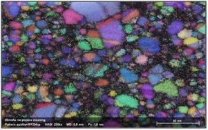
Figure 6A. IPFz map before plasma cleaning. Image Credit: Evactron (XEI Scientific)
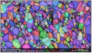
Figure 6B. IPFz map after plasma cleaning. Image Credit: Evactron (XEI Scientific)
Conclusions
The new series of Evactron remote plasma cleaners is currently available for cleaning SEMs and FIBs faster and more fully when compared to the initial models introduced in 2000. Turbomolecular-pumped SEMs and FIBs can be plasma cleaned at lower pressures in comparison with diffusion pumped units.
Lower-pressure operation enables longer distance penetration by oxygen radicals to clean bigger chambers. The flowing afterglow UV also increases the effective cleaning regions and speeds up the oxidation of hydrocarbons. Consequently, concentrations of higher oxygen radicals can reach contaminated surfaces inside all recesses of a chamber.
Smaller-sized PRS heads can be more closely attached to the chamber wall among numerous sensors and accessories without any disturbance. Installing the remote PRS proximal to the chamber wall port boosts the cleaning rate by reducing the recombination of oxygen radicals before they arrive at the main vacuum chamber.
Curves and corners in the connecting tube considerably decrease oxygen radicals. If input gas flow is constant because of reduced radical recombination and increased intensity of the flowing afterglow UV, the rates of plasma cleaning with air also increase at lower pressures.
Cleaning rate and radical density rely on chamber geometry and distances, radical production and recombination rates, pressure and means free path, source type and efficiency, flowing N2 afterglow, radical flux scattering and UV intensity for triggering the removal of surface contamination.
References
- Joubert, L. M. (2013). Microscopy and Analysis, May, 15-20.
- Morgan, C. G., Gleason, M. M., Vane, R. (2007). Microsc. Microanal. 13(2), 1736.
- Gleason, M. M., Morgan, C. G. Vane, R. (2007). Microsc. Microanal. 13(2) 1734.
- Morgan, C. G., Gleason, M. M, Vane, R. (2007). Microscopy Today, 15(5), 22.
- Morgan, C. G. and R. Vane. (2012). Microsc. Microanal. 18(2), 1238.
- Vane, R. (2013). Microsc. Microanal. 19(2), 1338.
- RR Keller and RH Geiss, J. Microscopy 245(3) (2012) 245-251.
- The authors thank Dr. Daniel Goran of Bruker Nano GmbH and teams from the Technical University of Denmark DTU-Danchip company and DTU’s Center for Electron Nanoscopy in Copenhagen, Denmark for generously providing the EBSD/TKD data.

This information has been sourced, reviewed and adapted from materials provided by XEI Scientific.
For more information on this source, please visit XEI Scientific.