A paradigm shift occurred in Paris in the late 17th Century, as the speed of light that thinkers, such as Descartes and Aristotle, had speculated as being infinite and instantaneous had been empirically found to show delays.
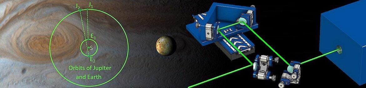
Image Credit: PI (Physik Instrumente) LP
By observing eclipses of Io - the Jovian Moon – the basis of what would become the first practical measurement of the speed of light was conducted using an optical delay from a variable path length.
Now, extremely precise path length control in optical delay lines is an essential element of techniques such as Fourier Transform Infrared Spectroscopy (FTIR) and transient absorption spectroscopy (using pump-probe).
The Importance of Miniscule Time Increments
Dynamic processes in materials and chemical compounds can be studied precisely using time-resolved spectroscopy. It is possible to view these changes using ultra-short pulse lasers, with timescales down to the attosecond range.
The calculation shown below demonstrates that a 10 nm step in a free space delay line adds a delay of ~.07 femtoseconds. In solid materials like optical fibers, this delay will be dependent on the material’s optical properties.
Nanopositioning capabilities are, therefore, essential in order to control a delay line in the femtosecond and attosecond range.
Fundamentals of Optical Delay Lines – Distance and Time
The diagram below illustrates the fundamental operating principle of a free space optical delay line.
The path is shown at Position X (green path) and follows a minor linear translation to Position X’ (purple path). It should be noted that the green path overlaps part of the purple path.
This diagram can be used to calculate optical path length difference and any corresponding optical delay:
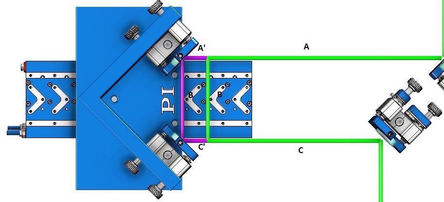
Basic principle of an optical delay line stage with kinematic beam reflector mirror mounts. Image Credit: PI (Physik Instrumente) LP
1. X=A+B+C (green path length)
and
2. X’=A+A’+B+C’+C (purple path length)
And path length difference is given by:
3. X’-X=A+A’+B+C’+C – (A+B+C)=A-A+B-B+C-C + A’ + C’ = A’+C’ (but A’=C’, the incremental motion step)
This equation results in:
4. X’-X=2A’
With the time domain, the optical delay is given by:
5. t= 2A’/c (where c is the speed of light)
In basic terms, this illustrates the importance of Minimum Incremental Motion (MIM) capability in the selected linear translation stage because this drives the optical delay in terms of temporal delay resolution.
MIM is a standardized motion term representing the smallest consistent and reliable step that it is possible to make with the stage.
V-508 Series of Direct Drive Linear Translation Stages for Optical Delay Line Applications
The influence of minimal incremental motion on optical delay line time resolution makes it a central guiding specification in PI motion solutions found in a wide range of spectroscopy, microscopy and interferometry applications.
The V-508 Series of Linear Motor Translation Stages is frequently the solution of choice for optical delay line applications.
These stages’ direct-drive design and direct metrology linear encoder successfully eliminate drive train errors that are frequently found in screw-drive type linear stages, geared or stepper motors; for example, backlash, play and non-linearities.
The V-508 Series is ideally suited for integration in optical delay lines combining PI proprietary nanopositioning technologies. This combination of technologies can achieve sub-nanometer resolution as well as single nanometer MIM.
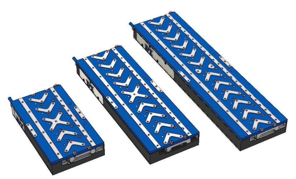
V-508 linear translation stages come in 3 travel ranges up to 250mm. Linear motor stages with up to 1200mm are also available. Image Credit: PI (Physik Instrumente) LP
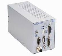
A compact single axis closed-loop motion controller for 3 phase direct-drive motor stages. Many controller options are available, covering different applications such as complex multi-axis coordinated motion, high speed automation, etc. Image Credit: PI (Physik Instrumente) LP
PIOne Direct Metrology Linear Encoders
PIOne interferometric linear encoder technology is able to provide ultra-high resolution position feedback at the moving platform.
This technology enables direct metrology sub-nanometer resolution measurement as well as excellent performance along with metrics such as repeatability, MIM, accuracy and position stability.
Linear incremental encoders’ resolution represents the smallest measurable displacement that the sensor head can discern along the scale. This measurement is dependent on the scale’s pitch (signal period), its electronic noise level and its electronic signal interpolation factor.
Lower noise enables higher interpolation without a loss of performance, but this is also subject to physical limitations. The most effective means of achieving a higher resolution is to utilize a smaller signal period.
The PIOne sensor can achieve better than 20 picometer resolution, based on its extremely short signal period of 0.5 µm and its advanced signal processing circuits – it allows 4000X interpolation without noise limitations.
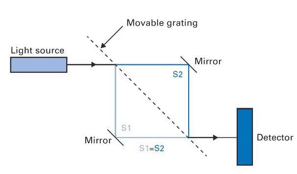
Schematic diagram of a Mach-Zehnder interferometer with equalized beam paths. A beam coming from a laser diode is split into two optical beam paths when passing between two gratings and then, united to a single beam again. The created interference pattern is detected by a photodiode and then processed further. Image Credit: PI (Physik Instrumente) LP
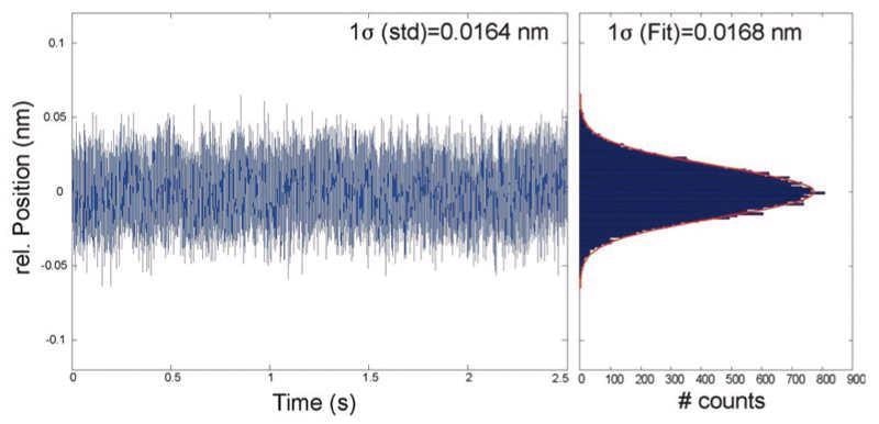
Ultra-low noise, measured in a nanopositioning stage with a PIOne encoder at 1 MHz bandwidth and 18-bit sensor input resolution: The result is 16 picometer RMS and 100 picometer peak-to-peak. Image Credit: PI (Physik Instrumente) LP
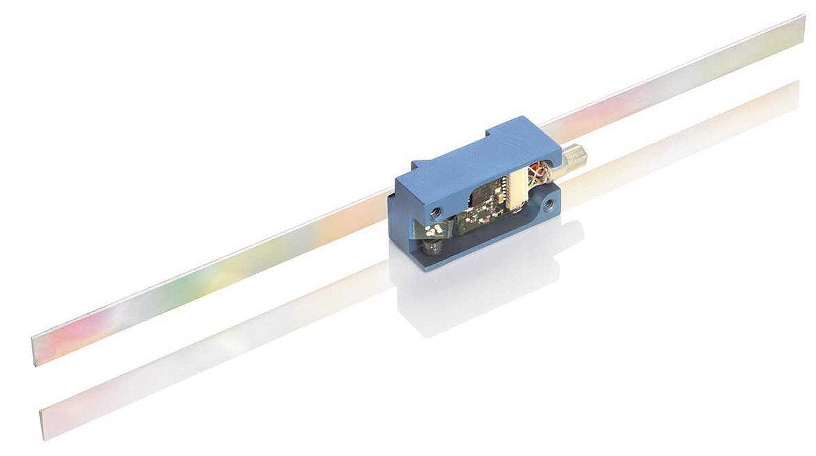
A PIOne linear encoder. Image Credit: PI (Physik Instrumente) LP

The interferometric read head is available for different requirements: Blue: 0.5μm signal period, for velocities ~200 mm/sec; silver: 0.5μm signal period, for vacuum conditions; red: 2μm signal period, for velocities >800 mm/sec. Image Credit: PI (Physik Instrumente) LP
Center-Driven Ironless Linear Motor and Precision Crossed Roller Bearings
V-508 linear translation stage employs compact, center-driven ironless linear motors to offer dynamically-responsive, smooth and ripple free nanopositioning capabilities whilst avoiding the inherent motor cogging characteristics that commonly limit motion performance.
These features are supported by hardened steel crossed roller bearings fitted with precision ground anti-friction guideways.
These finely-machined surfaces positively impact friction characteristics while minimizing stiction, ultimately facilitating a 1 nm MIM motion. These linear motors provide excellent position stability despite their high velocity. In order to provide such precision, extensive tests during production with nano-metrology equipment are necessary. For consistent performance nano-measurement standards and methods were developed, capable of characherizing these stages.
Linear Motor Stage, Direct-Drive Linear Stage, Nanopositioning Optical Delay Line Stage, V-508 | PI
Video 1. V-508 direct drive linear stages are available with 3 travel ranges and different encoder and linear motor options. Highest performance is achieved with the non-cogging ironless 3-phase electromagnetic linear motors and the PIOne interferometric linear encoders. Video Credit: PI (Physik Instrumente) LP
XY-Stage - Direct Drive Linear Stage w/Linear Motor, fast Scanning & Alignment, V-508 Linear Stage
Video 2. Performance capability of two XY-stacked V-508 linear stages in a high-speed, high accuracy optical alignment application. Video Credit: PI (Physik Instrumente) LP
Compact Design for Effortless Integration
The V-508 leverages an innovative design to offer a low profile and exceptional compactness while simultaneously integrating oversize bearings with extended operating life at rated load. These features make the V-508 ideal for cycled motions.
Low Profile, Non-Interfering Cable Exit
The instrument’s static cable exit and its linear translation stage’s extremely low profile support straightforward integration with marginal impact on optical path layout.
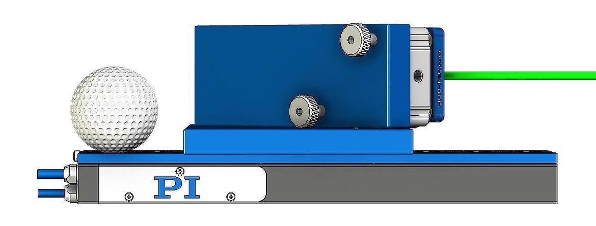
Low profile - comparison to a golf ball. Image Credit: PI (Physik Instrumente) LP
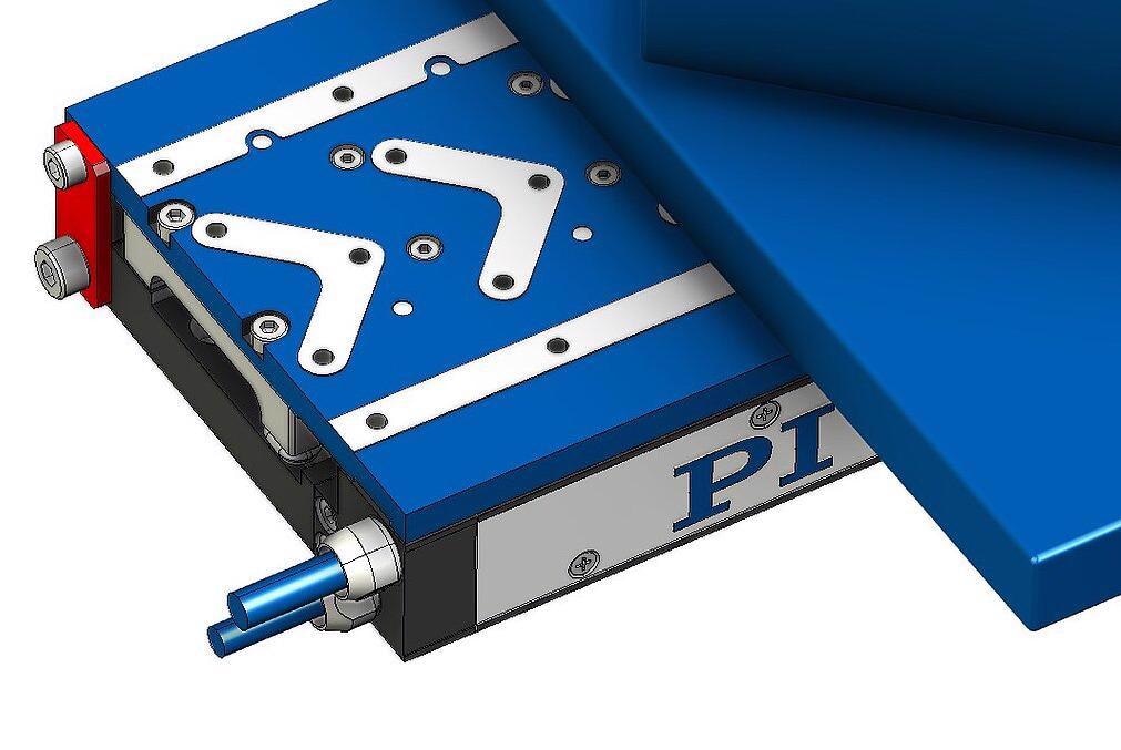
The static cable exit does not interfer with the optical setup. The red part on the left is the transport lock. Image Credit: PI (Physik Instrumente) LP
Key Optical Delay Line Specifications of the V-508 Translation Stage Family
V-508 Optical Delay Line Specifications
Table 1. Source: Image Credit: PI (Physik Instrumente) LP
| Model |
V-508.251020 |
V-508.651020 |
V-508.951020 |
| Travel |
80 mm |
170 mm |
250 mm |
| Encoder Resolution* |
0.2 nm |
0.2 nm |
0.2 nm |
| MIM |
1 nm |
1 nm |
1 nm |
| Bi-Directional Repeatability |
±0.05 µm |
±0.05 µm |
±0.05 µm |
| Max Velocity |
600 mm/s |
600 mm/s |
600 mm/s |
| Minimum Optical Delay |
0.007 fs |
0.007 fs |
0.007 fs |
| Maximum Optical Delay |
530 ps |
1134 ps |
1668 ps |
| Pitch |
±100 µrad |
± 200 µrad |
± 300 µrad |
*interpolated
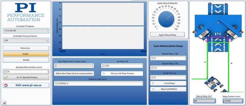
Optical Delay Line Stage Software interface, lets the user define a home position, delay in femtoseconds and program different delays to cycle through. Image Credit: PI (Physik Instrumente) LP

This information has been sourced, reviewed and adapted from materials provided by PI (Physik Instrumente) LP.
For more information on this source, please visit PI (Physik Instrumente) LP.