The optics of particle counters and the transportation of particles in tubing between a sample inlet have often been at the center of discussion concerning the accuracy of readings.
The reliability of the result is continually in question when the validation implications of losses due to a range of forces are evaluated. This article identifies the forces, the losses, and examines what results are acceptable to enable a better understanding of the challenge.
External Influences
Forces Acting on Particles
Cleanroom monitoring and certification activities can be seen as investigations conducted to measure the dynamics of the body of air inside an enclosed space. This space can be either the air in a laminar flow zone, a transport duct or in the general cleanroom.
The following outlines the processes of how particles function and will help in the understanding of sampling challenges and in optimizing the speed of sampling.
The Stokes number is the ratio of the radius of a particle to the measurement of a hindrance to the flow of fluid. This is a crucial element in establishing when a particle in motion will pass around an obstacle or will be collected by it. An obstacle may be the sample inlet or a filter fiber.
The drag coefficient is the ratio of gravity’s force to the inertial force on a particle in fluid. It shows how a particle will withstand any force that may alter the velocity of a particle. As a result of their decreased mass, particles that are smaller have smaller drag coefficients.
The relaxation time is the time taken for a particle to reflect a change in fluid velocity where it was first equal to a moving fluid. A longer relaxation time is observed in larger particles.
When a stream of air travels through tubing that includes small-radius elbows or bends, the large particles will accumulate on a tube wall as they fail to easily adapt to quick alterations in velocity as a result of tube curvature but will continue in their initial direction until they deposit on the wall of the tube.
Stopping distance is a related term that describes the distance at which a particle first moving inside a gas stream comes to a stop when the flow of gas is interrupted, for example, by an obstacle.
The sedimentation velocity or deposition velocity is the ratio of particle flux, the distance per unit of time for sedimentation to arise in relation to the ambient concentration of particles.
Table 1. Settling velocities of particles. Source: Particle Measuring Systems
| Particle Size (μm) |
Settling Velocity (cms-1) |
| 0.00037 |
- |
| 0.01 |
6.95 x 10⁻⁶ |
| 0.1 |
8.65 x 10⁻⁵ |
There are additional forces that have an influence on particles. These particle forces and their subsequent reaction to these forces direct the migration of particles through the air. These include:
Viscous Forces
The dynamic force of fluid from a fluid stream in motion. As the air stream has a viscous nature, particles will be pulled across that flow path. Additional forces influence the larger particles encouraging deposition and settling when this flow is laminar. In a laminar flow, the smaller particles continue to be buoyant.
In flow streams that are turbulent, if the larger particles deposit, they are re-entrained back into the airflow which makes the smaller particles more vulnerable to the extra forces acting upon them.
Brownian Motion
Sudden impacts from single molecules will cause particles to travel away from their course as they migrate through a body of air.
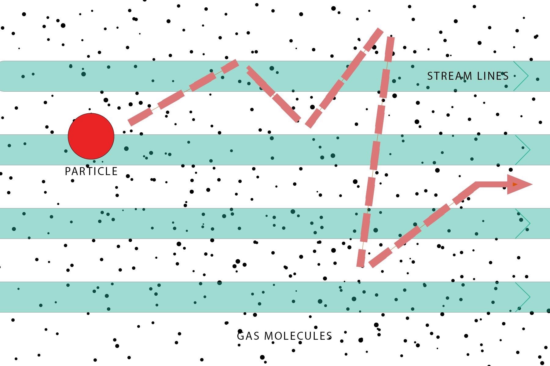
Figure 1. Image Credit: Particle Measuring Systems
Gravitational Force
This force on a particle differs from the variation between air and particle density along with particle mass, where a stronger interaction is shown by larger particles.
Electrostatic Forces
This force on a particle depends on the strength of the electrical field in which the particle resides and the electrical charge (surface area controlled) of a particle.
When a particle moves through the air stream, electrostatic charge can be produced. It is critical to reduce these interactions to make sure that all particles travel to the end location.
Diffusion Forces
This particle force differs inversely from the radius of a particle. Particles that are smaller are more vulnerable to diffusion interactions.
Thermophoretic Forces
These forces (most effective for small particles) differ with the temperature gradient and the surface area of a particle.
The reaction of the particle to these forces is dependent on the particle’s mass, size, electrical charge and shape. For almost all these forces, the key particle measurement is size, as the magnitude of the different forces changes according to particle size cubed or squared.
Practical Considerations
There are multiple methods to create a system to reduce these forces and their influence on sampling mistakes.
Isokinetic Sampling
In ducts leading to a filter, or in laminar flow environments, the air is thought to be traveling in one direction. When this air flow is sampled, it must neither be under or over the particle distribution inside of that flow.
The use of isokinetic sampling solves this requirement. Isokinetic sampling means that the air velocity in the sample-tubing inlet of the particle counter is equivalent to the air velocity in the supply air.
A negative or positive sample collection error happens if these velocities are different. An isokinetic sample error is more likely as the size of the particle increases but is not a significant risk to particles under 1–2 μm.
Federal Standard FS 209E1 explains that for particles less than a few micrometers, isokinetic sampling errors of more than 5% are unlikely when utilizing a sample probe with 2 mm or larger inlet diameter, even when sample and sampling air velocities vary by an order of magnitude.
Isokinetic sampling is required when macro particles greater than 5 μm are to be quantified. Particle Measuring Systems has a calculator that precisely measures the isokinetic probe’s dimensions and the related errors if a sample probe is employed that does not meet the standard.
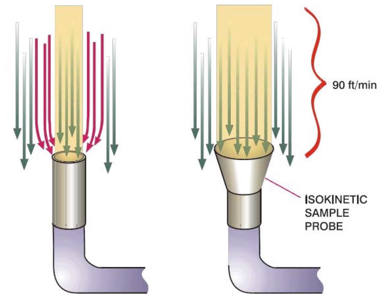
Figure 2. Image Credit: Particle Measuring Systems
Particle Loss in Transport Tubing
When a sample is acquired for either standard monitoring or certification tests, it is common for the isokinetic sample probe (ISP) to be remotely located from the particle counter optics.
In this case, the sample is taken from the tubing to the particle counter. Particle losses can happen in the transport tubing when the sample is to be moved any long distance in the tube from the sampling to the measurement point.
The losses depend on the flow velocity, tubing type, distance and tubing diameter. Large particles can be lost by a mix of inertial deposition on the tubing walls or gravitational settling to the bottom of the duct when changes in direction arise.
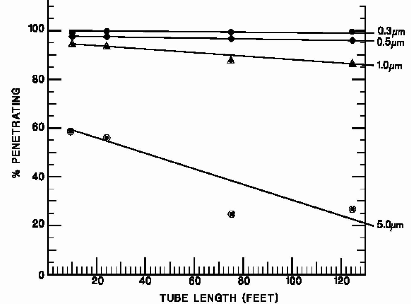
Figure 3. Image Credit: Particle Measuring Systems
Small particles can be lost to the duct walls through the effects of diffusion and Brownian motion.
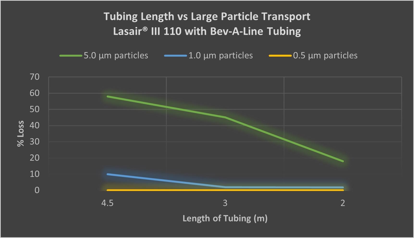
Figure 4. Image Credit: Particle Measuring Systems
The flow rate in the tubes is strongly decreased when portable particle counters are utilized, such as the Lasair® III. This means that the greatest allowable distance is also decreased.
Figure 4 demonstrates a similar pattern of this for manifold sampling but over distances that are much shorter.
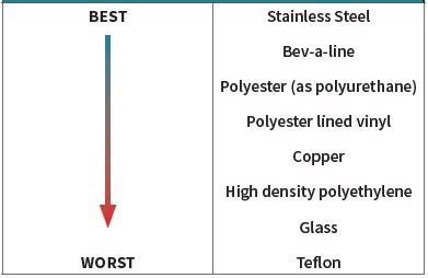
An amount of the particle loss is also a result of electrostatic forces. Different material types were assessed in order to determine an appropriate standard to decrease the influence of these added forces.
The tubing material’s preference order (Table 2) depends on a combination of electrical conductivity, potential for sulfide or oxide formation when the tubing is exposed to urban air and the rate of particle loss.
Table 2. Particle transport line material preference. Source: Particle Measuring Systems
The tubing’s diameter should be chosen to make sure that the Reynolds number is in the range of 5,000 and 25,000 as specified in FS 209E1. For particles less than 5 to 10 μm, the Reynolds number is a range at which no strong or turbulent deposition can arise.
The length of time in the tubing should not exceed 10 to 20 seconds, allowing particles greater than 0.1 μm to transmit before any high amount of losses arise.
Acceptable Losses
This chapter is the most challenging to determine because any loss may be considered as unacceptable. This section will evaluate the acceptable errors and uncertainties for particle counting.
Table 3 presents a comparison of different standards on the topic of airborne particle counting. While not completely adopted, they describe the errors and how a build-up of errors can easily show how particle counters can vary from each other.
In Table 3, a range of errors are presented from 35% to 81% where the average error is predicted to be around 50%. If this is added to an acceptable loss of an isokinetic sampling of 5% for counts, then the errors for particle transportation is comparatively small.
Whether it be a manifold-based system or a 28.3 LPM (1 CFM) system, when qualifying particle losses, the ability to calculate systematic errors is very simple and biasing of data is relates to the distance apart, probe orientation, amount of particles being sampled, air flow patterns, base line variables between counters, optical variances, test duration, and more.
As such, it is challenging to determine an absolute allowance.
Table 3. Error analysis for various counting standards. Source: Particle Measuring Systems
| |
JIS B9921:1997 |
ISO-13323-2 |
ASTM f328-98 |
| Particle Size Accuracy |
|
5% |
|
| Particle CV |
|
5% |
|
| Sizing Accuracy |
5% |
10% |
|
| Counting Efficiency |
20% |
20% |
10% |
| Sample Volume |
10% |
10% |
5% |
| Resolution |
|
10% |
10% |
| Coincidence Level |
5% |
10% |
|
| Flow Rate Accuracy |
5% |
5% |
10% |
| Time Accuracy |
1% |
1% |
|
| Volume Accuracy |
|
5% |
|
| Total Error % |
+/- 46% |
+/- 81% |
+/- 35% |
As a general guide, making sure that any sampling errors are a minimum of 50% of the maximum allowable counting error (50%), means the total error should not be significantly impacted by any sample that measures an environment in at least 25% efficiency of transportation loss.
Given that the predicted particle counting losses qualification exercise is more than 25% loss, this is the same as approximately 7.0 m for a manifold device (Aerosol Manifold II-16) or 2.0 m for a 28.3 LPM particle counter (Lasair® III, Airnet® II 510) which means acceptable values for particles of 5.0 μm can be calculated.
Acknowledgments
Produced from materials originally authored by Mark Hallworth from Particle Measuring Systems.
References and Further Reading
- Airborne Particulate Cleanliness Classes in Cleanrooms and Clean Zones, Federal Standard No. 209E. Washington, DC: General Services Administration, 1992.

This information has been sourced, reviewed and adapted from materials provided by Particle Measuring Systems.
For more information on this source, please visit Particle Measuring Systems.