As technology advances, the demand for smaller features and more intricate semiconductor designs grows. Consequently, the manufacturing processes must adapt.
Laser-Assisted Wafer Slicing
Lasers play a crucial role in various applications in semiconductor manufacturing, such as laser cutting and slicing. The integration of lasers enhances throughput and improves defect control, leading to sustainable higher yields.
Wafer Stealth Dicing / Motion Control for Laser Based Semiconductor Wafer Dicing
Wafer Stealth Dicing / Motion Control for Laser Based Semiconductor Wafer Dicing. 5-DOF Stage for Wafer Stealth Dicing / Semiconductor Wafer Dicing. Video Credit: PI (Physik Instrumente) LP
Traditionally, slicing SiC ingots into wafers involves diamond- or slurry-based wire sawing processes, resulting in significant kerf-loss of valuable material and increased wafer costs.
On the other hand, laser cutting utilizes ultra-short pulse lasers to condition a specific layer within the material, creating a weakened region for controlled cleaving of the entire wafer from the ingot.
By optimizing laser parameters and beam delivery, manufacturers can control material deformation without causing thermal damage to the top and bottom interfaces of the sliced wafer.
External forces, such as bonding force and pressing force, guide cracks to precisely split the material along the laser-conditioned layer.
Advantages in Comparison with Traditional Wafer Cutting Techniques
Laser-modified cutting emerges as a fast and cost-efficient solution to the growing demands and cost challenges in the semiconductor industry.
This technique eliminates the typical kerf-loss associated with wire saws during the ingot-to-wafer slicing process, resulting in a significant yield improvement in SiC wafer production without requiring an expansion of crystal growth capacities. Additionally, it facilitates the production of sub-100 µm thin SiC devices.
PI XY-Theta Stage: 3-DOF Motion System to Help Laser Slicing Processes
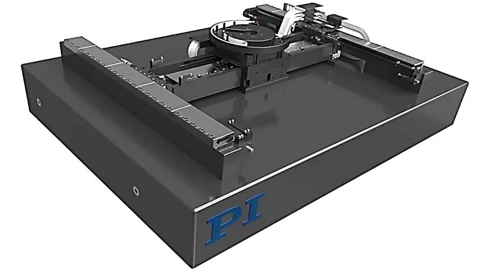
3-DOF, granite-based XY-Theta stage using direct drive motors and air bearings for the highest possible accuracy, speed, and lifetime. Image Credit: PI (Physik Instrumente) LP
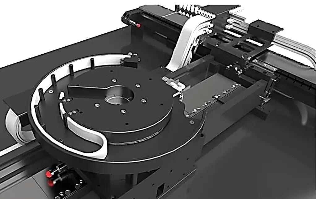
Close-up of the low-profile Theta-Z rotary stage. Image Credit: PI (Physik Instrumente) LP
A-322 High-Performance XY Planar Stages and Motion Systems
The A-322 High-Performance XY Planar Stages and Motion Systems is a top-notch system sporting a flat granite base that excels in dynamics and guiding accuracy, serving as an optimal platform for the most demanding ultra-precision laser processing needs.
This motion platform boasts 3 ironless linear motors devoid of cogging, paired with 3 high-resolution, low CTE absolute encoders (1nm resolution) outputting BiSS-C signals.
It glides smoothly on a thin film of laminar air, ensuring frictionless and dynamic motion, a necessity for tracing intricate trajectories.
Precision Gantry Control: Advanced Motion Algorithms, Active Yaw Control: for XY & XYZ Gantries
Advanced Gantry Stage - Motion Control Algorithms: XY & XYZ Gantry Stages, Active Yaw Control. ACS advanced 3-DOF gantry control algorithm explained with the A-322 XY-Theta stage. Video Credit: PI (Physik Instrumente) LP
With a configuration of 3 motors and 3 encoders, it combines linear and rotational axes (X, Y, Theta-Z), streamlining control loops for both types of motion. This configuration maximizes throughput and performance without loop interference.
The stage integrates a flexure coupling between the X and Y axes, permitting up to +/-0.5° of Theta-Z rotational motion. This motion compensates actively for yaw, enhancing overall performance and operational simplicity.
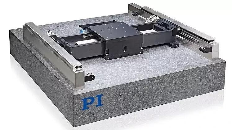
The A-322 planar XY stage is available in travel ranges up to 500 mm × 1000 mm. Its flexure coupling of the cross axis allows for +/-0.5° Theta-Z motions, very useful for error correction or alignment. This feature is available with the ACS motion controllers. Image Credit: PI (Physik Instrumente) LP
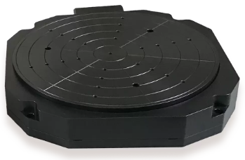
For larger rotation angles, a low-profile rotary table, such as the A-634, or a custom design, can be added on the A-322 cross axis. Image Credit: PI (Physik Instrumente) LP
A-322 Product Variants
A-322 Product Variants come in three performance levels within the planar XY + Theta stage product family:
- A-322 XY Stage Base Model. Includes all the aforementioned features, utilizing medium-sized linear motors for moderate dynamic performance. Acceleration: Up to 0.5g (based on payload).
- A-322 XY Stage Plus Model. Enhances the base model by employing larger linear motors with water cooling for increased speed, acceleration, and duty cycle performance. Cooling water needs to be supplied by the customer. Acceleration: Up to 2.0g (based on payload).
- A-322 XY Stage Ultra Model. Further improves the Plus model by adding a 4th motor and encoder (added to the X axis) to achieve enhanced accuracy and repeatability suitable for larger payloads, like flat panel applications.
Self-locking Feature Provides Higher in-Position Stability
A dynamic solenoid valve can be added to the stage to manage the vertical lift air supply for the cross-axis air bearing. By activating or deactivating the lift air supply while keeping other air supplies operational, the stage's position can be securely fixed.
Using vacuum preload vertically generates locking force through friction against the granite. This locking occurs while the servo loops are active, preventing unintended movement in the X-Y directions during the transition.
A-63X High-Performance Air Bearing Rotation Stage
PI's low-profile rotary air bearing stages (such as models A-634, A-635, and A-638) feature a high-performance 3-phase brushless direct drive torque motor. These stages offer optimal dynamics and motion performance, ensuring exceptional positioning accuracy through high-resolution, direct-measuring absolute and incremental encoders.
Despite being compact and lightweight, the rotary tables are designed to provide remarkable stiffness and handle high loads. The tabletop, precisely ground flat, minimizes distortion, while the motion platform is designed to support 200 mm, 300 mm, and 450 mm wafers and panels.
ACS-Based Motion Controller with State-of-the-Art Features
The ACS-based A-8XX multi-axis motion controllers feature advanced motion profiling algorithms, enabling the creation of intricate optimized trajectory paths. These paths are precisely tracked through tight servo loops equipped with real-time disturbance attenuation, leading to superior process outcomes.
The motion control solutions from ACS, utilizing Laser Control Modules (LCM) and Laser Control Interfaces (LCI), enable high-speed and tightly synchronized laser triggering, enhancing accuracy in laser micromachining applications.
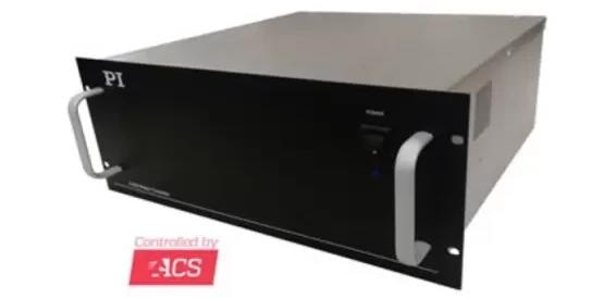
High-performance multi-axis motion controller family: A-824 – 4-axis configuration, A-826 – 6-axis configuration and A-828 – 8-axis configuration. These controllers can run on incremental encoders and absolute encoders. Image Credit: PI (Physik Instrumente) LP
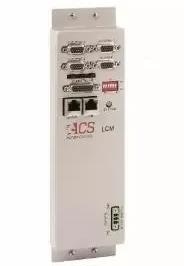
The laser control module (LCM) can be integrated in the A-82x motion controllers. LCM tightly synchronizes control of a fixed beam laser with motion. Sub-microsecond latency enables high-accuracy laser micromachining, while high pulse frequencies enable high levels of throughput. Image Credit: PI (Physik Instrumente) LP
Test Data of an XY-Theta Air Bearing Stage
The test data and graphs presented below are a subset of the tests conducted by PI during the qualification process of a multi-axis air-bearing stage. Additional information is available upon request. This test report provides an overview specifically for an XY-Theta air-bearing 3DOF stage.
Test report overview for an XY-Theta air bearing 3DOF stage. Source: PI (Physik Instrumente) LP
X-axis (gantry axis) dynamic straightness, < 0.450 μm pp (over center 300 mm at 300 mm/sec). Measured with 20 kg load, 0.75 g max acceleration. Image Credit: PI (Physik Instrumente) LP
Y-axis (cross axis) dynamic straightness, < 0.500 μm pp (over center 300 mm at 300 mm/sec). Measured with 20 kg load, 0.75 g max acceleration. Image Credit: PI (Physik Instrumente) LP
X-axis accuracy: 0.18 µm. Image Credit: PI (Physik Instrumente) LP

Y-axis accuracy: 0.29 µm. Image Credit: PI (Physik Instrumente) LP
Y-axis following error at 500 mm/sec velocity and 0.75 g acceleration. Image Credit: PI (Physik Instrumente) LP
Y-axis following error at 800 mm/sec velocity and 0.75 g acceleration. Image Credit: PI (Physik Instrumente) LP
Theta-axis (spindle) repeatability: ±1 µrad; accuracy: 3.5 µrad. Image Credit: PI (Physik Instrumente) LP
Theta-axis spindle radial error: 0.036 µm. Image Credit: PI (Physik Instrumente) LP

This information has been sourced, reviewed and adapted from materials provided by PI (Physik Instrumente) LP.
For more information on this source, please visit PI (Physik Instrumente) LP.