Long-distance motor racing has evolved into a testing ground where engineers strive to achieve the optimal blend of performance and durability, allowing brands to cultivate confidence in their operations and products.
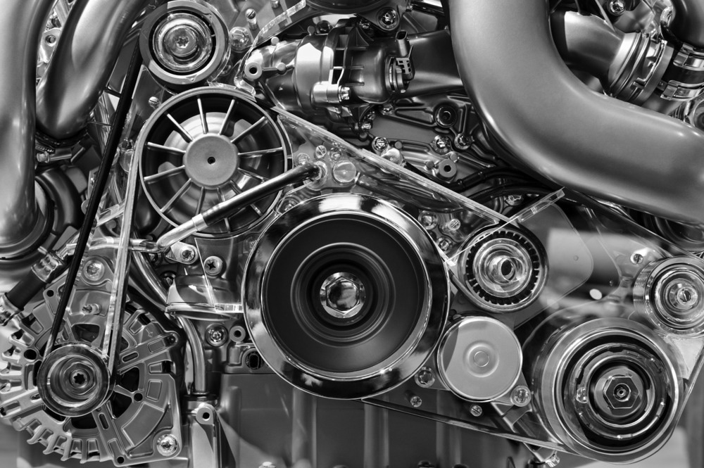
Image Credit: AMatveev/Shutterstock.com
While research and development teams in the automotive sector strive to integrate art, science, and engineering into cutting-edge technologies, including hybrid and fully electric propulsion systems, their colleagues in industrial precision motion control work just as relentlessly to push the limits of the possible.
Despite the remarkable capabilities of modern precision motion systems—utilized in manufacturing advanced chip technology—triumphs here rarely earn trophies.
In this context, tolerances are often measured in nanometers. This precision is propelled by Moore's Law, which consistently calls for smaller feature sizes in each successive generation of chips. Similarly, tolerances in high-performance engine parts are steadily shrinking toward the micron scale.
Despite enhanced output and efficiency, there are still concerns regarding longevity. For many performance car enthusiasts, the prospect of reaching 100,000 miles on the odometer marks both a significant milestone and a source of apprehension regarding future reliability.

Long-distance travel – to the moon and back. Every component must meet the highest quality standards. Image Credit: NASA

Clicking the miles away - 1 million miles feasible for a precision linear motion stage? Image Credit: Physik Instrumente
Load and Inertia are the Enemies: The Parallels of Precision Automation and Performance Cars
Precision automation systems bear a remarkable resemblance to high-performance sports cars. The parallels of dynamic performance, cornering, stiffness, precision stopping (step-settle), and weight are combined with micron and sub-micron scale tolerances for repeatability and trajectory following.
In both scenarios and when examined on a larger scale, the operational lifespan of car engines and motion systems exhibits striking similarities. It’s widely understood that running a reciprocating engine at higher RPMs places greater stress on materials and causes a non-linear increase in load on bearings, which significantly impacts their longevity.
Consequently, high-revving race engines, despite using top-notch materials, sophisticated design and production methods, and the highest quality control standards, have a notably shorter service life between rebuilds compared to their low RPM counterparts used in everyday utility or transportation settings.
Before delving into the relationship between load and lifespan in precision linear motion stages, such as those in high-performance automation applications, it may be valuable to journey back to Germany in the 1820s.
Mine Carts and Microns
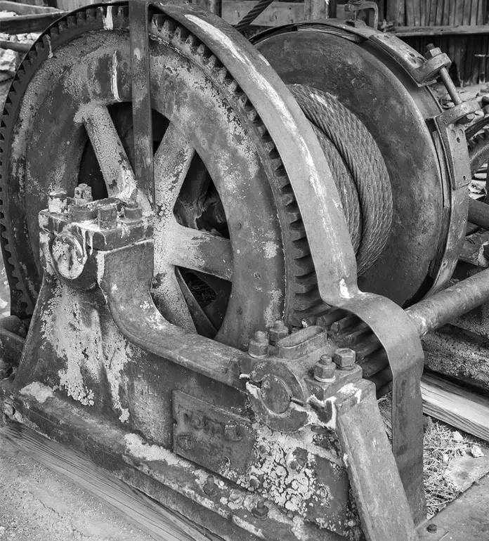
Mine cart hoist from the past. Image Credit: Wikipedia
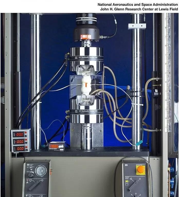
Modern fatigue test machine. Image Credit: NASA/Wikipedia
In the 1820s in Germany, the initial systematic exploration of metal fatigue was underway, focusing on chains used in mine cart cable hoists. During this time, they noticed that repetitive, cyclical, and light loading caused failure. It seemed as if the chain became tired or fatigued. This observation remains true today: metals exposed to cyclical stresses and strains will develop cracks and fractures over numerous repetitions, limiting their lifespan.
In modern precision automation tools that use stages with mechanical bearings, similar concerns arise regarding rolling contact fatigue, resulting in material damage to the bearings. This damage is usually seen as fatigue flaking in the raceway or rolling elements.
Enhancing bearing life involves various aspects, including the use of hardened bearing steel (with resistance to rolling contact fatigue and corrosion), appropriate lubricant chemistry, optimized integration, environmental conditions, preloading, correct relative sizing, tolerancing of coupled surfaces, and loading layout.
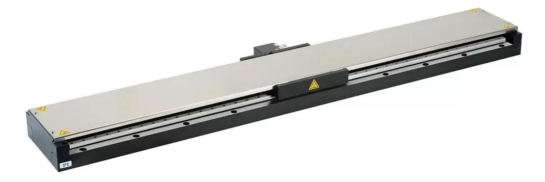
V-817 is a high-performance single-axis linear stage for precision industrial automation. This unit employs direct-drive, friction-free 3-phase linear motors, removing common drive-train-related sources of wear and tear, such as ball screws, tooth belts or gearboxes. Image Credit: Physik Instrumente
A Brief Quantitative Look at Bearing Life
To help explain how bearing life is quantified in a “million-mile” stage design, the V-817 Linear Motor Stage Series is used as an example. To start, it is important for the type of bearings used in the V-817 to understand the equation that governs bearing life of this type:
L=50*(C/(fw*P))3
C is an empirical constant specific to the bearing, defining the load under which the bearing can consistently achieve an operating life of 50,000 km. A higher value means a longer rated life under lower specific applied load conditions.
P represents a load intended to mimic a continuous single applied force, representative of the various loads acting overtime on the bearing that would produce a similar estimated lifetime.
Fw is the load factor applied based on the operating environment. In high vibration or shock environments, this value can exceed 1 (up to 3), while in quiet environments, it is typically around 1-1.2 (optimal).
The main takeaway of the above equation is the cubic relation of lifetime and load–reducing the load by 50% increases bearing life by 800%. This insight is crucial in selecting the appropriate stage for the task. A stage with double the required load capacity will significantly prolong its lifespan.
Anatomy of a Million Mile Linear Translation Stage
The V-817 linear translation stage utilizes precise truck and rail bearings equipped with recirculating balls. Its dual rail setup positions the carriage on the corners in a rectangular layout, ensuring an even distribution of the load across all four trucks to minimize moment loads.
Unlike some other bearing types, this type of bearing is fully supported throughout its entire travel, reducing moment loads near travel ends.
The bearings on the V-817 positioning stage boast a Basic Dynamic Load Rating of 1330 N (equivalent to approximately 135 kg when normally applied) for each rolling element.
In a situation with a normal applied load and minimal center of gravity offset, where each rolling element carries a quarter of the load without creating moment loads, the Dynamic Load Rating effectively surpasses 500 kg. To ensure an extended operating life, the V-817 stage is rated for 60 kg loads, considering various loading scenarios.
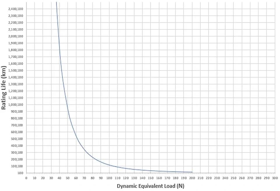
Bearing life vs. dynamic equivalent load. Image Credit: : IKO
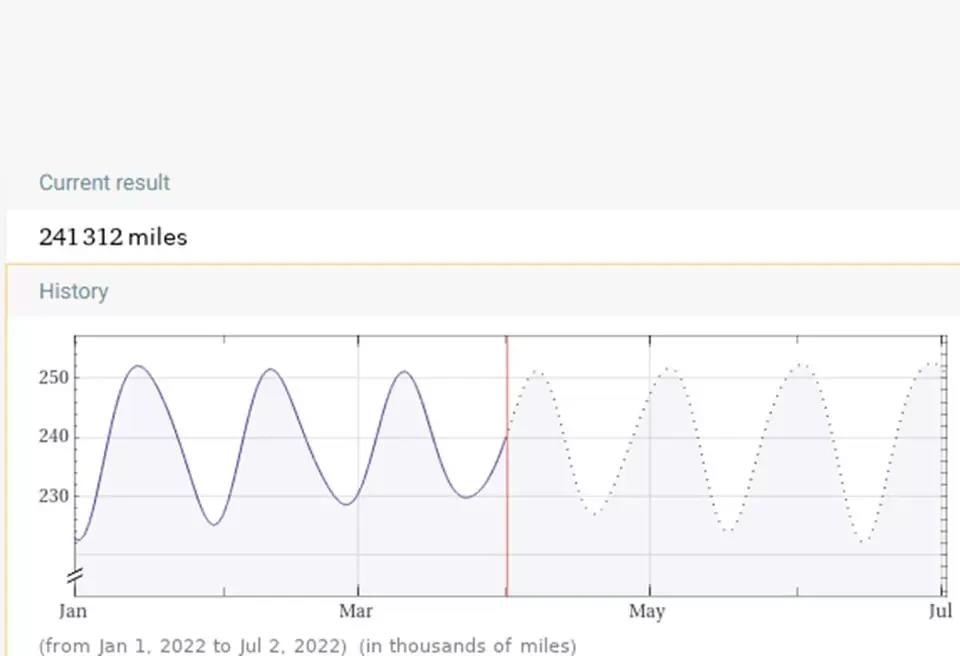
Distance Earth to Moon. Image Credit: Wolfram Alpha
In precision motion systems, a common term used is “moving mass,” which refers to the load applied to the bearings that necessitate movement. This typically includes the inherent attributes of the stage (carriage coupled to bearings) along with the applied load on the carriage. In the case of the V-817, the approximate moving mass is 2.2 kg.
The payload weight varies depending on the application’s needs, but a common value is around 10 kg. Consequently, the total moving mass in this scenario is approximately 12 kg. For the sake of this straightforward example, let us assume that the center of gravity (CG) of the applied payload is positioned at the center and the moment loads are approximately negligible.
Under the scenario where weight is evenly distributed, each rolling element in the dual rail, four-truck arrangement of the V-817 linear translation table carries a load of 3 kg (equivalent to 29.4 N when applied).
Based on the rated life/load curve for the bearings, calculated using the provided equation, an estimated rating life of about 4.4 million km or 2.7 million miles is observed.
To put this into perspective, the typical cyclical distance to the moon is around 240 thousand miles, meaning theoretically, the stage could make approximately ten trips without experiencing fatigue failure.
Mileage May Vary
The above points show what is possible in ideal situations with a centered load. When there is a protruding weight, it creates a twisting force and adds pressure on individual bearings.
For highly dynamic applications, it is advisable to maintain a low center of gravity to minimize moment loads during acceleration and deceleration. In motion control, much like in the context of high-performance cars, the significance of a low center of gravity design is inversely correlated with the demands placed on dynamic performance.
Companies making performance cars often test their products rigorously on the Nürburgring Nordschleife track, stressing all mechanical parts to the maximum. While most cars would not survive pushing their limits there for even 10,000 miles, achieving 100,000 miles under normal conditions poses no challenge.
While precision motion stages may not undergo a Nürburgring-style test, strategies such as load centering, the elimination of redundant material from mounting hardware, and lowering the center of gravity can yield substantial benefits in terms of longevity, particularly in the context of round-the-clock, 24/7 automation.
Multi-Axis Assemblies: Why a Wide Base is Better?
The V-817 series linear stages are commonly assembled into XY or XYZ Motion Tables, where the bottom axis supports the upper axis and payload.
A wider base, especially on the lower stage, enhances the XY-table’s geometry (straightness, flatness, pitch, yaw, and roll) and extends bearing life by reducing moment loads. 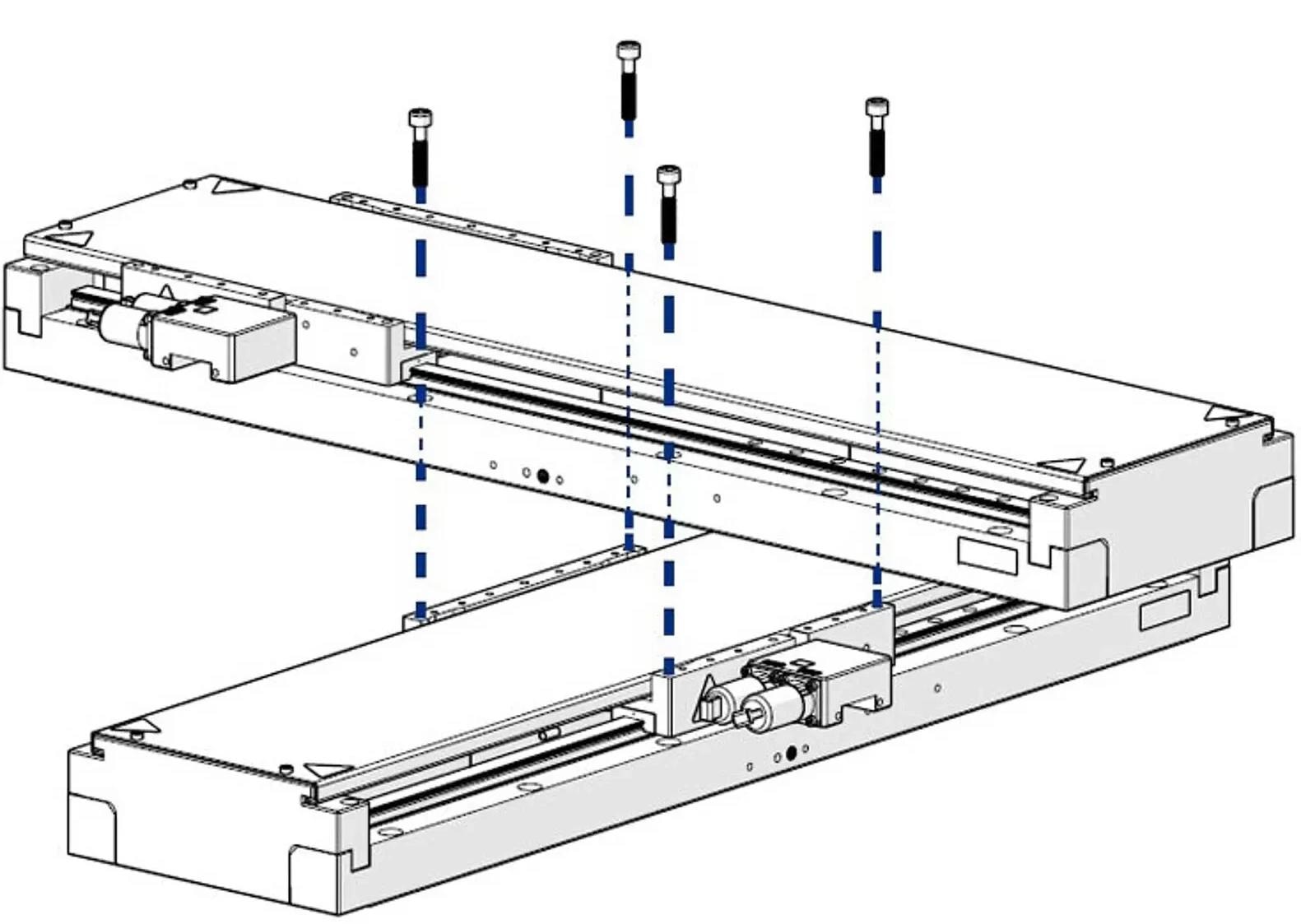
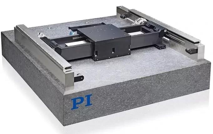
V-817 stages are designed for direct XY mounting without the need of a moving platform on the lower axis. This has two positive effects on the lifetime: a) reduced moving mass, b) lower center of gravity. Image Credit: Physik Instrumente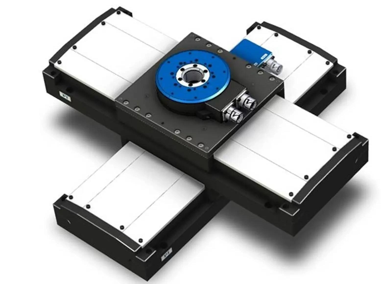
3-axis-stage assembly, based two V-817 linear units mounted in XY-table configuration and a V-610, direct-drive rotary stage. Due to the wide base of the V-817 stage, this combination works well for 200mm Y-travel ranges, as shown above. Image Credit: Physik Instrumente
Other Configurations for XY Motion
A basic XY stage stack might not suffice for extended Y-axis travel needs. Instead, consider two parallel X-axis stages, a split bridge design, or a gantry system.
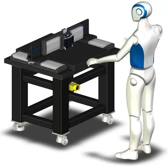
Low profile XY+ gantry configuration based on three V-817 linear motor stages. Image Credit: Physik Instrumente
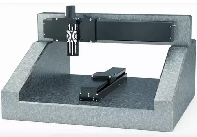
Split-bridge XY+Z granite motion system. Image Credit: Physik Instrumente
Gantry-type planar XY air-bearing table. This type of XY stage provides the best geometric performance. Image Credit: Physik Instrumente
A Final Word
Like any idealized scenario, real-world implementation demands several practical considerations and expectations.
Bearings need proper lubrication and protection from contaminants and debris. Temperature fluctuations and shocks, vibrations, and other dynamics affect stress/strain and can cause premature fatigue-related failures.
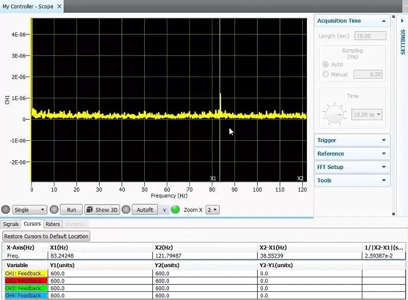
The Fast Fourier Transform (FFT) of stage positioning error shows an external vibration source injecting an error signature at approximately 85 Hz into the stage servo. These kinds of environmental disturbances can have a negative impact on operating stage life. PI provides software tools to quickly characterize these types of external influences to optimize system design and prepare a quiet environment to get the most from the lifetime of performance automation tools. Image Credit: Physik Instrumente
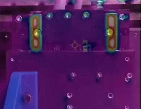
Anti-friction guides and lubrication are useful to prevent thermal cycling-induced stress/strains that accelerate rolling fatigue failure. Repetitive motions on a direct drive stage show bearings are the hottest elements in this thermal image. Image Credit: Physik Instrumente
The Moon is Not Enough
If your precision automation application requires travel distances beyond what is achievable with conventional means, consider air-bearing stages. In contrast to mechanical bearings, air bearings are free from friction and wear, and lubrication is no longer an issue.

This information has been sourced, reviewed and adapted from materials provided by Physik Instrumente.
For more information on this source, please visit Physik Instrumente.