Various types of piezoelectric ceramic motors, like resonant motors and inertia motors, serve as the driving force in precision motion systems. They are often used in compact precision linear translation stages and rotary positioning stages.
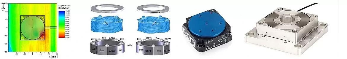
Image Credit: Physik Instrumente
This study focuses on the direct-drive ultrasonic resonant motors called PILine® motors. Their direct-drive design enables ultra-low response times and highly precise positioning without any backlash.
PILine® ultrasonic ceramic motors operate on a preloaded principle, allowing them to maintain a position even when powered off. Moreover, these piezoceramic drives are unaffected by magnetic fields and do not produce any magnetic fields.
This article delves into the utilization of PILine® precision motion stages in environments with strong magnetic fields or where the drive must remain neutral magnetically.
1. Operating Principles of PILine® Ceramic Motor Positioning Systems
At the core of every PILine® motor-driven linear or rotary stage lies a piezoelectric actuator preloaded against a runner using a coupling element (refer to Fig. 1).
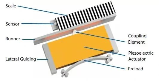
Figure 1. Schematic design of a PILine® ultrasonic direct-drive piezo motor: A piezoelectric ultrasonic transducer is preloaded against a runner. The piezo transducer is stimulated to oscillate by an electric high-frequency current. These oscillations are converted into a forward motion that is transmitted to the runner via a coupling element. Image Credit: PI (Physik Instrumente) LP
The piezoceramic transducer deforms when an electric field is applied due to the inverse piezoelectric effect. This deformation occurs at a crystalline level within the material and remains unaffected by magnetism. Thus, PILine® ultrasonic motors do not interact with magnetic fields.
These characteristics enable piezoelectric motors to operate in two application fields:
- Operation in strong magnetic fields
- Use in a sensitive environment without influencing existing magnetic fields
While piezoelectric motors can function in open-loop mode, they lack defined “indents” like stepper motors. A position sensor (linear or rotary encoder) is incorporated for precision positioning with high repeatability to provide feedback to a closed-loop motion controller.
Typical PIline® motor-driven linear stages, such as the U-780 XY microscope stage, offer travel ranges up to 135 mm. Depending on size and encoders, velocities of 200 mm/second and resolutions of 10 nm are achievable.
Regarding rotary tables like the U-651 utilizing two rectangular piezo transducers at 180-degree spacing, a closed-loop angular velocity of up to 540 deg/second with 4 µrad encoder resolution can be attained. When “at rest”, or powered down, the piezoceramic motors are self-clamping with excellent in-position stability.
Another benefit of piezoelectric direct-drive motors is their compact size, enabling the creation of highly precise yet small linear and rotary stages. Subsequently, this article will explore the behavior of the U-624 miniature rotary stage, the second smallest standard rotary stage offered by PI based on an ultrasonic motor.
Precision Motion Control w/ Ultrasonic Piezo Motors: - Closed-Loop Linear Stages, Rotary Stages | PI
Precision Motion Control w/ Ultrasonic Piezo Motors: Closed-Loop Linear Stages, Rotary Stages| PI. Functional principle of ultrasonic linear motor stages and rotary stages, showing the bending modes of rectangular and ring-shaped piezo transducers and force transmission. Video Credit: PI (Physik Instrumente) LP
2. Materials in Magnetic Fields
When a material is placed in a magnetic field, it begins to physically interact with it. This interaction can either significantly alter the intended magnetic field or interfere with the functioning of electro-mechanical systems present in that magnetic field.
If these interactions are adverse, conventional electromagnetic motors cannot be used, and instead, so-called “nonmagnetic” drives are employed.
In nature, there are various forms of magnetism that cause different degrees of physical interaction.
2.1 Differentiation between Diamagnetic, Paramagnetic, and Ferromagnetic Materials1, 2, 3
Materials are categorized into three types based on their magnetic properties, which are primarily determined by the interactions within the material when exposed to an external magnetic stimulus. The classification of these materials is influenced by the mathematical relationship of their internal responses to the magnetic field.

The magnetic flux density B (or, colloquially, magnetic field) is connected to the magnetic stimulus H through permeability, comprised of the constants µ0 and material-specific relative permeability µr.
In everyday life, the magnitude of the magnetic flux density ranges from the strength of the earth’s magnetic field with 20-70 µT to magnetic resonance scanners with 7T.4,5
Diamagnetic materials form a field that opposes the external stimulus. This is because the moving electrons in the material are deflected by the external field, causing the buildup of a field that opposes the external field. This opposition occurs when the relative permeability is less than 1.
The diamagnetic effect is subtle, disappears when the external field is removed, and is often overshadowed by paramagnetic or ferromagnetic effects. One example is the levitation of pyrolytic graphite above permanent magnets.
For paramagnetic materials, microscopic dipoles align in the external magnetic field, intensifying the field in the material. Paramagnetic materials are drawn into the field when µr > 1. On removing the external field, the effect also disappears.
Ferromagnetic materials act similarly to paramagnetic ones but with a notable difference: after removing the external field, they retain a “remnant polarization,” generating their magnetic field. These materials can exhibit a high relative permeability (µr >> 1), reaching values up to 106.
Forces observed in ferromagnetic materials surpass those found in diamagnetic and paramagnetic ones and are particularly evident in neodymium iron boron permanent magnets, showcasing a strong magnetic interaction.
Therefore, in positioning systems that are not meant to influence the magnetic field, only diamagnetic and paramagnetic materials should be used. In other words, materials with a relative permeability of approximately 1.
Using such materials ensures minimal influence from internal magnetic fields on external applications or positioning systems. Therefore, avoiding (strong) ferromagnetic materials in non-magnetic applications is advisable if possible.
2.2 Selecting Materials – Typically Used Materials for (Non) Magnetic Applications
When selecting materials for (non)magnetic applications, understanding their relative permeability is crucial in establishing a magnetic field-insensitive system. Commonly, plastics and ceramics exhibit diamagnetic properties, while metals may display paramagnetic or ferromagnetic traits.
The table below showcases materials suitable for non-magnetic setups, such as those involving the PILine® drive.
Table 1. Material values for relative permeability µr. Source: PI (Physik Instrumente) LP
| Material |
µr |
for |
Source |
| Air |
1.00000036 |
N/A |
[2] |
| Metals |
|
|
|
| Aluminum |
1.000021 |
7 T |
Calculated from [6] |
| Copper |
0.9999904 |
7 T |
Calculated from [6] |
| CuBe2 |
1.00002 |
N/A |
[7] |
| CuSn6 |
0.99999912 - 1.000062
(0 – 0.09 % Fe) |
N/A |
Calculated from [8] |
| Gold |
0.999966 |
7 T |
Calculated from [6] |
| Silver |
0.999976 |
N/A |
Calculated from [9] |
| 96/4 SnAg |
1.00000060 |
7 T |
Calculated from [6] |
| Titanium (Grade 1) |
1.000178 |
N/A |
[10] |
| TiAl6V4 (Grade 5) |
1.00005 |
N/A |
[10] |
| Tungsten |
1.000070 |
N/A |
Calculated from [9] |
| Ceramics |
|
|
|
| Al2O3 |
0.999986 |
7 T |
Calculated from [6] |
| PZT |
0.9999942 |
9.4 T |
Calculated from [11] |
| Si3N4 |
0.999986 |
7 T |
Calculated from [6] |
| SiC |
0.999988 |
N/A |
Calculated from [9] |
| ZrO2 |
0.9999915 |
N/A |
Calculated from [9] |
| Plastics |
|
|
|
| FR4 PCB |
0.9999963 |
9.4 T |
Calculated from [11] |
| Kapton |
0.9999911 |
9.4 T |
Calculated from [11] |
| PA6 natural |
0.9999905 |
9.4 T |
Calculated from [11] |
| PEEK |
0.9999907 |
9.4 T |
Calculated from [11] |
| PPS |
0.9999908 |
7 T |
Calculated from [6] |
| PTFE (Teflon) |
0.999990 |
9.4 T |
Calculated from [11] |
| PVC, grey |
0.999989 |
9.4 T |
Calculated from [11] |
During cold forming, austenitic corrosion-resistant steels undergo a transformation, resulting in the formation of friction or deformation martensite. This process changes the material’s magnetic properties, significantly increasing its μr from a low value in its original state to a much higher one.
For instance, 1.4305 is a material that clearly demonstrates this behavior, with its relative permeability ranging between 1.05 and 3.42, contingent upon the extent of deformation.
This factor necessitates careful consideration, especially when employing austenitic corrosion-resistant standard parts where information regarding the level of cold deformation is often unavailable.
Table 2. Material values for the relative permeability µr for different degrees of deformation of 1.4305. Source: PI (Physik Instrumente) LP
| Degree of Deformation |
µr |
for |
Source |
| 0% |
1.003 |
N/A |
[12] |
| 10% |
1.050 |
N/A |
[12] |
| 20% |
1.620 |
N/A |
[12] |
| 30% |
3.420 |
N/A |
[12] |
3. Tests and Measurement of Precision Rotation Stages in Magnetic Fields13
The Research Center Jülich (Forschungszentrum Jülich) has been using rotation stages equipped with PILine® piezo motors for high magnetic field applications.
A crucial aspect of their work involved assessing the impact of the positioner on the precise characterization of dipole magnets, ensuring that the positioner’s presence did not adversely affect the accuracy of the magnet characterization process.
To address this, the researchers tested both a standard U-624.03 PILine® rotary positioner and a specialized modified version tailored for nonmagnetic settings. The U-624.03 miniature rotation stage, compact with a 30 x 30 mm² footprint and a 12 mm height, is ideal for space-constrained applications.
The following illustrates the measurement setup and the results from the investigations at the Forschungszentrum Jülich.
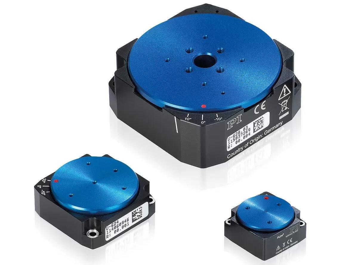
Figure 2. A family of miniature rotary stages driven by ultrasonic ceramic motors. The U-624.03 used for the tests is the one in the lower left corner. Image Credit: PI (Physik Instrumente) LP
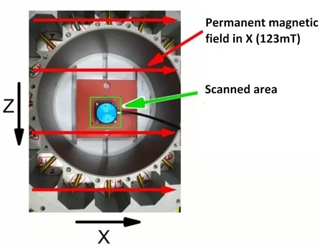
Figure 3. Measuring setup for magnetic measurement of the rotation stages. Image Credit: PI (Physik Instrumente) LP
3.1 Measurement Setup
Positioner magnetic evaluations occurred in a Forschungszentrum Jülich measuring chamber, as depicted in Figure 3.
A permanent external magnetic field of 123 mT was generated, oriented along the positive x-axis. The resulting magnetic field component in the Y direction was mapped out in the region highlighted in green, approximately 1 mm above the rotor surface of the PILine® rotary stages. Throughout this process, the cable was consistently positioned on the right-hand side of the setup.
3.2 Measurement Results
Initially, the U-624.03 standard rotation stage underwent assessment within the 123 mT external magnetic field containing ferromagnetic elements. This allowed measuring Y-direction field component values, ranging from -800 to 800 µT approximately 1 mm above the rotor level.
The subsequent figure illustrates this measurement, depicting the external contour as a square, the positioner’s rotor as a circle, and the cable as a right-pointing line.
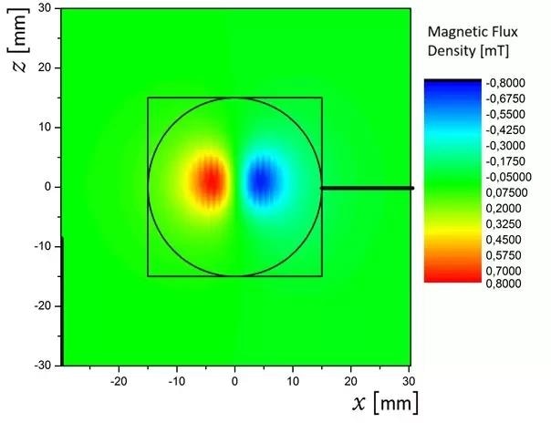
Figure 4. Magnetic flux density across the standard U-624.03, COTS miniature piezo motor rotation stage. Image Credit: PI (Physik Instrumente) LP
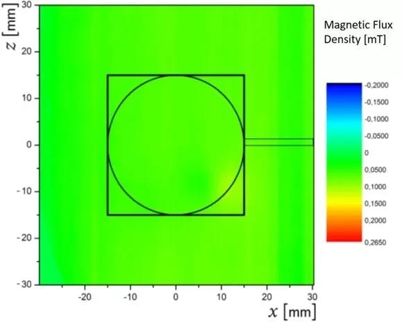
Figure 5. Magnetic flux density across the modified mini rotation stage, measurement 1. Image Credit: PI (Physik Instrumente) LP
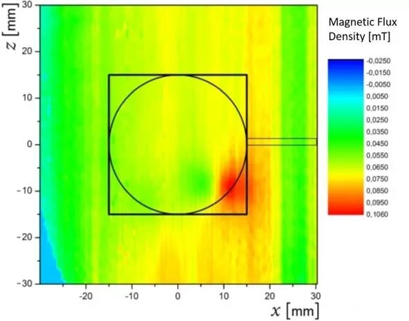
Figure 6. U-624 was modified, measurement 2, and the highest resolution range. Image Credit: PI (Physik Instrumente) LP
The standard stage showed two poles (seen as red and blue areas in Fig 4) where field lines were vertical to the image plane, entering or exiting it. A chromium steel ball bearing near the rotor surface in the standard rotation stage caused these elevated measurement values.
For the modified U-624 rotator, all ferromagnetic components were replaced with low relative permeability suitable substitutes.
Changes were made to the all-ceramic ball bearings, titanium screws, and internal PCB components. The magnetic field measurements described earlier were repeated using the updated rotary positioner.
In the initial measurement, despite using a broader range of -200 to 265 µT (Fig. 5), no visible effects on the positioner’s components were observed; the magnetic field seemed uniformly distributed.
Consequently, a second measurement was conducted, employing an even finer resolution and a range of -25 to +106 µT, revealing notably lower field values (Figure 6).
In the bottom right corner of Figure 6, a maximum stray field of 106 µT stemming from the modified U-624 positioner is depicted, resulting from the integrated encoder head necessary for precise stage operation.
The alterations allowed for an approximately 87% reduction in the measured magnetic field compared to the standard COTS unit, marking 106 µT as a remarkably low value. Hence, the modified positioner is suitable for various non-magnetic applications.
4. Function Tests in External Magnetic Fields13
At the Forschungszentrum Jülich, the investigations included not only measurements of magnetic flux density but also functional tests of the rotary stage under high magnetic field conditions.
When it came to characterizing dipole magnets, it was essential for the positioners to be capable of maneuvering a measuring probe within the high magnetic field. This capability is crucial for the precise characterization of the dipole magnets.
Both the off-the-shelf (COTS) and custom U-624 PILine® rotation stage (detailed in Section 4) underwent testing. A PI C-867.1U closed-loop motion controller, managed by PIMikroMove® software, operated these stages.
4.1 Measurement Setup
The setup involved mounting the miniature rotary positioners on a plastic block and inserting them into the gap of a dipole magnet with a maximum static field of 1.8 T. The magnetic field direction was vertical or aligned parallel to the rotation axis, positioning the stage in the middle of the dipole field (refer to Fig. 7).
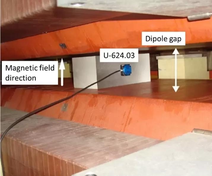
Figure 7. Large Dipole Magnet with U-624.03 miniature rotary stage. Image Credit: PI (Physik Instrumente) LP
4.2 Measurement Results
Both stages functioned effectively in reference mode and position control mode, remaining error-free up to the maximum magnetic field of 1.8 T.
Throughout the process, the stages consistently operated within specifications, whether aligned perpendicularly or parallel to the rotation axis. Rotation speeds of up to 720 °/second at 1.8 T were also successfully tested.
5. Summary
When an electro-mechanical system interacts with a magnetic field, it can significantly affect the field, or conversely, the magnetic field can potentially damage or disrupt the system’s functionality.
In selecting a closed-loop piezo-motor positioner for use in magnetic fields, the material choice and its non-magnetic properties hold substantial importance.
The relative magnetic permeability µr serves as a crucial measure of the material’s interaction with the magnetic field. Systems intended for such environments should ideally comprise materials with a µr value close to 1.
The magnetic flux measurements conducted in this study affirmed the exceptional non-magnetic characteristics of a modified rotation stage based on PI’s U-624 model. This investigated positioning system exhibited smooth and reliable operation even in high magnetic fields of up to 1.8 T.
PILine® ultrasonic piezoceramic motors operate using the inverse piezoelectric effect, where ceramic transducer deformation occurs at a crystalline level, remaining impervious to magnetism.
Beyond linear motion stages and rotary systems, PI also offers non-magnetic multi-axis stages and custom motion systems.
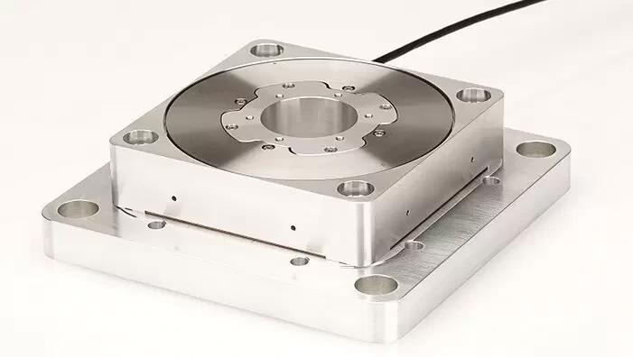
Figure 8. A non-magnetic version of the U-653 rotary stage. Image Credit: PI (Physik Instrumente) LP
PI Closed-Loop Rotary Tables: How Ultrasonic Transducers in Direct Drive Miniature Rotation Stages
PI Closed-Loop Rotary Tables: How Ultrasonic Transducers in Direct Drive Miniature Rotation Stages. Basic design of encoded miniature rotary stages based on ring-shaped piezo-transducers and direct rotary encoder. Video Credit: PI (Physik Instrumente) LP
Acknowledgments
Produced from materials originally authored by Thomas Polzer from Physik Instrumente (PI) GmbH & Co. KG.
References and Further Reading
- W. H. Hayt Jr. and J. A. Buck, Engineering Electromagnetics, 8th edition, New York: McGraw-Hill, 2012.
- N. Ida, Engineering Electromagnetics, New York: Springer science & business media, 2000.
- W. D. Callister Jr., Materials science and engineering: An introduction - 7th ed., New York: John Wiley Sons, Inc., 2007.
- Deutsches GeoForschungszentrum, "Magnetfeld der Erde - Unser dynamischer Schutzschild," [Online]. Available: https://media.gfz-potsdam.de/gfz/wv/doc/infothek/leaflets/Faltblatt_Magnetfeld_dt.pdf. [Zugriff am 20 07 2020].
- Siemens Healthineers, "Magnetresonanztomographie,“ Siemens Healthineers, [Online]. Available: https://www.siemens-healthineers.com/de/magnetic-resonance-imaging. [Zugriff am 16 11 2020].
- F. D. Doty, G. Entzminger and Y. A. Yang, "Magnetism in high-resolution NMR probe design. I: general methods," Concepts in Magnetic Resonance, Volume 10, Issue 3, pp. 133-156, 07 12 1998.
- NIPPON THOMPSON CO., LTD., "IKO: non-magnetic linear motion rolling guide series: CAT-5937," 2012. [Online]. Available: https://www.ikont.co.jp/global_data/download/pdf_catalog/cat5937.pdf. [Zugriff am 20 04 2020].
- Deutsches Kupferinstitut, "Werkstoffdatenblatt CuSn6," 2005. [Online]. Available: https://www.kupferinstitut.de/wp-content/uploads/2019/11/CuSn6-1.pdf. [Zugriff am 30 03 2020].
- D. R. Lide, et al., “Magnetic susceptibility of the elements and inorganic compounds” in CRC handbook of chemistry and physics, Boca Raton: Taylor & Francis, 2006.
- ThyssenKrupp, "Titan - Werkstoff mit Perspektive,“ 2012. [Online]. Available: https://www.thyssenkrupp-schulte.de/. [Zugriff am 09 05 2016].
- M. C. Wapler, J. Leupold, I. Dragonu, D. von Elverfeld, M. Zaitsev und U. Wallrabe, "Magnetic properties of materials for MR engineering, micro-MR and beyond," Journal of Magnetic Resonance, Volume 242, pp. 233-242, 08 04 2014.
- Informationsstelle Edelstahl Rostfrei, "Merkblatt 827 : Magnetische Eigenschaften nichtrostender Stähle," 2013. [Online]. Available: https://www.edelstahl-rostfrei.de/fileadmin/user_upload/ISER/downloads/MB_827.pdf. [Zugriff am 04 05 2016].
- I. Engin, "Bericht Forschungszentrum Jülich über die Charakterisierung der Rotationstische," intern, 2016.

This information has been sourced, reviewed and adapted from materials provided by Physik Instrumente.
For more information on this source, please visit Physik Instrumente.