For many years, lasers have been used for welding and cutting in material processing. However, laser technology has long been regarded as a specialist field, necessitating complicated control systems for precise positioning, as well as significant investment and experience.
In recent years, lasers have become more affordable, opening up this powerful technology to new applications; even the most recent rapid ultrashort pulse lasers are now feasible options for machine builders who would previously have used 'less hazardous' laser setups.
The commoditization of lasers requires system integrators to do more to achieve and maintain an advantage; positioning and control, as vital components of any laser system, are important to achieve this.
The newer technologies work in a slightly different way, so it stands to reason that positioning and control should be different as well. The basic ability to fire the laser in the right place has become more difficult, and a simpler approach is more important than ever, especially for those who are completely new to technology.
Novel solutions are now available that take a uniquely modular approach to laser control, making it easier and faster for system integrators to design and implement systems in the first place, regardless of whether they have prior experience with lasers.
The use of industrial control networks like EtherCAT increases the flexibility of such a modular solution by allowing for the easy incorporation of other objects, such as sensors or non-motion devices.
This article considers laser positioning and motion control in laser processing applications, the issues that system integrators confront, and, most crucially, the solutions available to them to simplify system construction.
Why Choose Laser Processing?
Lasers have many important advantages over traditional machining methods, notably their ability to achieve substantially higher throughputs.
They are not subject to the same wear and tear that can cause breakdowns, disruptions, and added costs, and they are usually effective when processing materials that are otherwise notoriously difficult to work with.
Lasers' fine beams can provide a level of detail and accuracy that is nearly impossible to achieve using other technologies, making them suitable for applications like producing high-aspect-ratio holes or other features that require such high precision.
High-intensity short-pulse lasers, in particular, are extremely precise, and the low thermal energy deposition around the beam causes negligible harm to the surrounding environment.
Lasers can process materials below the surface, depending on where the beam focuses: examples include light-emitting diodes and flexible screens.
Striking the Right Balance of Speed, Power, and Precision
Whatever the application, quick shuttering and precise laser pulse firing are critical for ensuring consistent, high-quality results. This requires precise positioning and energy control, which can be achieved by directly connecting the automation and motion system to the laser output.
It is important to ensure that the laser is focused on the correct location, for the correct period of time, and at the correct power level to avoid material damage or the manufacture of incorrect parts.
One possibility is to link laser power to pulse rate and modulation; if the power is fixed, the motion system must operate at a constant speed to ensure that the appropriate level is transmitted throughout the surface.
This is appropriate for some activities, such as raster scans, in which the laser is fired while moving in one direction or during the constant velocity period between acceleration and deceleration.
However, cutting and welding applications may require laser pulses to overlap at a consistent ratio, even if the motion path speed is variable and laser pulses occur at a given frequency.
Figure 1 shows an example of this: 1a shows laser pulse placement at a constant speed profile, and 1b shows when the velocity changes. This could lead to nonuniform pulse delivery, with too much energy going to one location causing HAZ (heat-affected zones) and too little causing weak sections or fractures in the cut or weld route.

Figure 1a. Laser pulse placement during a constant speed profile. Image Credit: PI (Physik Instrumente) LP

Figure 1b. Non-uniform pulse delivery. Image Credit: PI (Physik Instrumente) LP
The nonlinear route of corners or arcs makes HAZ a more common problem in multi-axis systems.
Imagine a sports vehicle driving around a racetrack; as it comes to a turn, it must slow down or it will be unable to keep the racing line and would most likely run off the track. The same is true for an XY table.
If the motion path slows down significantly while the laser pulsing rate remains constant, too much power is supplied into the corners when the laser pulses bunch together (Figure 2). Some G-code capable CNC machines offer 'look ahead' capabilities that allow the motion controller to detect speed changes that exceed predetermined restrictions.

Figure 2. Pulses bunching up around corners. Image Credit: PI (Physik Instrumente) LP
Linking Laser Control to Speed and Position
One of the most basic methods of adjusting laser power is to link it to the velocity of the motion route.
This is easily accomplished by connecting an analog output in the controller to the vector speed of the motion route and then to the laser power. The analog output is connected to the laser's power input connector, which has a 0–10 Vdc range.
Typically, the motion controller allows users to specify a scaling factor such that the maximum output is proportional to the maximum power of the laser required for the process. A lower limit can also be set.
It is vital to remember that jerks can lead to poor processing if the motion is not well regulated and that poor placement accuracy might also result in a low-quality item.
The outlined method is simple but effective for processes such as welding. Another way is to accurately control the laser by directing pulses along the motion route, regardless of vector velocity.
It is also possible to combine these two methods to manage power output scaling to overcome undesirable aspects of the laser electronics or optical path.
Several technologies exist in the industry that may provide such precise, high-speed, position-based events linked to electronic outputs, such as laser pulses. Although they differ slightly, they generally perform the same function for single-axis motion; some are more suited to galvo technology, while others are more suited to motorized positioners.
With the introduction of a new modular controller from PI's ACS line, position event generation (PEG) is emerging as an innovative and adaptable solution for connecting a laser to multi-axis positioning.
The Challenges of Controlling Multiple Axes
Three or more axes can be combined to form paths that create three-dimensional trajectories.
Examples include simple dual vector tracking, generated from two axes and widely used for linear XY stage contouring, including circles, arcs, and straight lines; a linear theta combination for processing tubing; and any combination of linear and rotary stages, such as producing helical motion for drilling.
Until recently, regulating the motion path of lasers across many axes has been constrained by performance, speed, practicality, and, most importantly, increased complexity and expense.
Restricted Application, Performance, and Speed
Many of the drives available for precision motion and laser processing must be preset, depending on the feedback device used on the stages or table in the motion system.
Positional feedback refers to a device that can read the location of the stage while also allowing the controller to determine its speed. Some motion stages do not employ feedback. Rather, they assume that the ordered motion request equals the actual response.
Feedback systems are typically either incremental or absolute. Incremental encoders require a reference point or known position when the device is turned on, which is usually a homing switch.
In comparison, an absolute encoder system incorporates positional data into the feedback measurement scale. This positional data is available upon startup, eliminating the need to physically relocate the system to a reference device.
Incremental Feedback Systems
There are two types of incremental encoders: square wave and sinusoidal (sin/cos wave) (Figure 3). Square wave encoders give the system distinct digital steps with a set distance.
A square wave encoder on a rotary motor can output 1000 steps every revolution. When driving a 1 mm pitch screw, the system resolution is 1 mm/1000, or 1 µm.
When a square wave encoder has a high count output, but simultaneously requires rapid speed, this can become a problem. The output frequency may exceed the maximum frequency input of the controller's feedback circuit, resulting in position loss.
Sine wave encoders can provide substantially higher resolution at higher stage speeds since the controller inputs data at the encoder's fundamental frequency, which is much lower than the square wave counterpart.
To generate the internal digital steps, the controller feedback circuit divides the sine wave internally into digital steps, a process known as multiplication.
In practice, a square wave encoder may begin as a sinusoidal encoder, with the primary difference being where the digitization or multiplication occurs: at the feedback device in the case of a square wave or in the controller.
Unfortunately, many laser firing controllers cannot use sinusoidal feedback to generate an output that will trigger the laser because their electronics require digital square wave signals, which may limit their usability in low-speed systems with high feedback resolutions or high-speed systems with low feedback resolution.
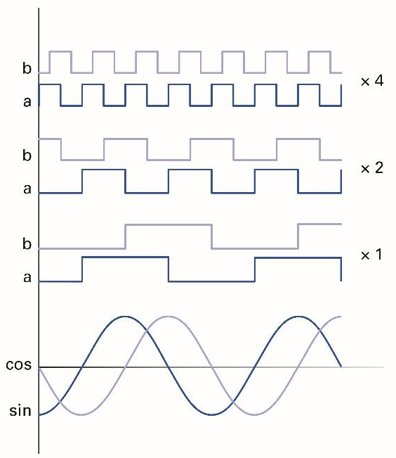
Figure 3. Sine wave encoder subdivision (encoder multiplication). Image Credit: PI (Physik Instrumente) LP
Multiple Feedback in Multi-Axis Systems
Laser synchronization technologies use encoder data for single-axis path motion to activate one-to-one firing, resulting in a single laser pulse for every millimeter or micron moved.
When it comes to multi-axis motion, such as pulsating in a circle, the same idea applies. Data is collected from each axis' separate encoders and supplied into on-board electronics circuitry, where the overall vector output is generated.
This has been the acknowledged norm for many years, and its precision is attributed to the fact that it is based on real-time positional data from encoders. However, if the motion system is not performing well, this strategy will yield unsatisfactory results.
For example, a constant speed circle on a gantry system or XY table is made up of sinusoidal velocity changes in each axis. A change in velocity indicates that there must be an acceleration connected with the motion. Acceleration is proportional to the following error (the difference between the commanded and real paths).
As a result, the path will always diverge from what was commanded, and it is the user's obligation to keep the error below the level for needed precision. The deviation may cause the path to be longer or shorter, resulting in the laser pulsing being activated at erroneous points.
The electronic circuitry used to process multiple feedback devices and create the output vector used for firing can cause a significant delay (latency) in the output; the more encoders tracked, the faster the output becomes, and the data input rate (tracking) of each feedback device decreases.
Non-Incremental, Non-Direct, or Non-Feedback Systems
Firing hardware that requires encoder data cannot be employed to generate events for motors without feedback, such as stepper motors.
Similarly, they are incompatible with serial communication-based absolute encoders. These encoders do not need to be 'homed' when they start up, which can be a considerable advantage in terms of safety and simplicity for some complex systems.
Kinematic systems, such as hexapods, are also difficult because the encoder data is not directly linked to the position or motion in a parallel direction, or it is a combination of data from multiple axes that requires calculation, and thus does not generate direct triggering for paths in Cartesian coordinates.
There are relatively few automation controllers on the market that can manage this level of complexity, ensuring that the motion system not only has proper motion performance but also the ability to read in and trigger out the encoders used in these applications.
With this in mind, users should think of pulsing tactics that do not rely entirely on immediate feedback. Regardless of the method chosen, the machine builder should always consider the mechanics and controller's motion performance.
Other system issues in motion systems include resonances, low bandwidth, underpowered motors, and mechanical inadequacies (such as accuracy, roll, pitch, yaw, flatness, straightness, and stacking areas) that must be appropriately matched to the system requirements for the workpiece or laser head to be in the correct position when firing.
The Drawbacks of Repurposing Drive Systems
Laser processing adds additional hardware requirements to an automation system, and the system designer must be aware of the input and output requirements when connecting a laser to a controller.
In theory, when a system integrator constructs a new system with enhanced laser control capabilities, the input/output capability of the master controller or master drive unit must be considered.
This is challenging since the focus shifts from required servo performance to laser connection functionality. Typically, the machine builder must rewrite the entire control system to accommodate these increased requirements.
This could include replacing the first drive unit with a physically larger, more sophisticated, and more costly drive that combines such characteristics (Figure 4). This can have a substantial influence on costs, including time spent redesigning the system, additional hardware, spare parts inventory, and larger electrical cabinets.
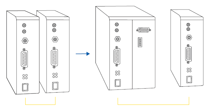
Figure 4. Replacing the first drive to create a multi-axis control system. Image Credit: PI (Physik Instrumente) LP
Download the full article now to learn more