Interest in piezoelectric ceramic motors has grown significantly in recent years, particularly in the semiconductor, optics, photonics, microscopy, medical, and life science industries, where precise motion and positioning are critical to product performance, measurement accuracy, and manufacturing yield.
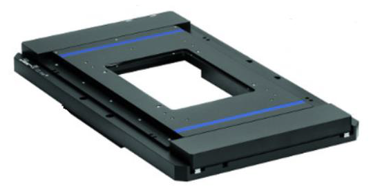
Image Credit: PI (Physik Instrumente) LP
Motion systems based on PI’s PILine® positioning technology integrate ultrasonic piezo motors to combine nanometer-level positioning precision with high-speed motion - a combination that few conventional drive technologies can achieve. This unique capability makes PILine systems well suited for applications requiring both fast throughput and exceptional positioning accuracy.
This article explores some of the most demanding motion-control applications in which PILine® ultrasonic piezo motor technology provides distinct advantages over conventional drive systems.
- Positioning with nanometer resolution
- Rapid step-and-settle within milliseconds
- High-speed pattern scanning
- Constant-velocity motion
- Slow and smooth motion
- Low position drift in standby mode
- Motion along predefined paths (sine, circles, arcs)
- Low-latency motion triggering and feedback
- Minimal wear and reduced power consumption
- Silent motion across all applications
2. Operating Principle of PILine® Ultrasonic Motors and Positioning Systems
PILine® precision positioning systems are based on ultrasonic piezo motors that provide direct-drive linear motion without gears, screws, or belts. A piezoelectric transducer vibrating at ultrasonic frequencies is preloaded against a runner through a coupling element (Figure 1). The frictional interaction between the transducer and runner converts the ultrasonic vibration directly into smooth, precise linear motion.
When the piezoelectric actuator is electrically excited at its resonant frequency, it begins to oscillate. Through the applied preload and coupling element, this oscillatory motion is converted into continuous linear movement of the runner.
The preload also gives the drive a self-locking characteristic when power is removed. Motion velocity is controlled by varying the excitation amplitude and, therefore, the amount of energy transferred to the runner.
Stage position is measured by an incremental encoder or, in some configurations, an absolute linear encoder. The encoder count is proportional to the distance traveled. With advanced sensor and grating technologies, sub-nanometer resolution is achievable.
PILine® stages typically operate in closed-loop mode. A proportional-integral-derivative (PID) control algorithm continuously compares the commanded position with the actual position measured by the encoder. The resulting position error serves as the input for the controller, which adjusts the drive signal to minimize trajectory deviation.
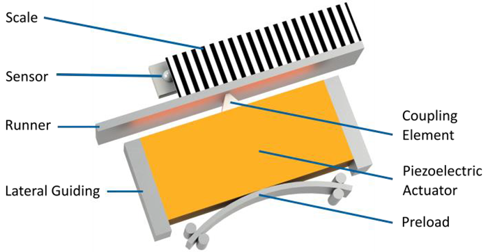
Figure 1. Schematic diagram of a PILine® ultrasonic motor: The piezoelectric actuator is preloaded against the runner. Electrical excitement of the actuator causes oscillation. This oscillation is converted to motion, which is then transmitted to the runner using a coupling element. The position of the runner is recorded by a stationary linear scale (encoder), which counts the periods of a grating attached to the runner. Image Credit: PI (Physik Instrumente) LP
3. Driving Methods of Ultrasonic Motion Systems
The stator of the ultrasonic piezo motor is a piezoelectric actuator operated at resonance. Its rectangular body, with dimensions of length × width × height, is made from bulk PZT material manufactured by PI Ceramic, a subsidiary of PI.
Three excitation electrodes are sputtered onto the actuator’s two main surfaces. One surface is fully covered, while the electrode on the opposite surface is divided into two equal sections. Exciting the actuator at one of its mechanical resonance frequencies generates elliptical motion at the coupling element.
The resonance frequencies are identified through impedance measurements. A low-level frequency sweep is applied to one of the two divided electrodes while the other remains electrically open. The measurement reveals two resonances within the ultrasonic frequency range (Figure 2).
At frequency f1, the motor’s primary operating mode, the coupling element follows an inclined, narrow elliptical trajectory that drives the runner. At frequency f2, the coupling element moves primarily back and forth in the tangential direction.
The best performance is achieved with adaptive control with Dual-Source, Dual-Frequency (DSDF) drive technology (see section 4). Refer to the PI website for controller compatibility and additional product information.
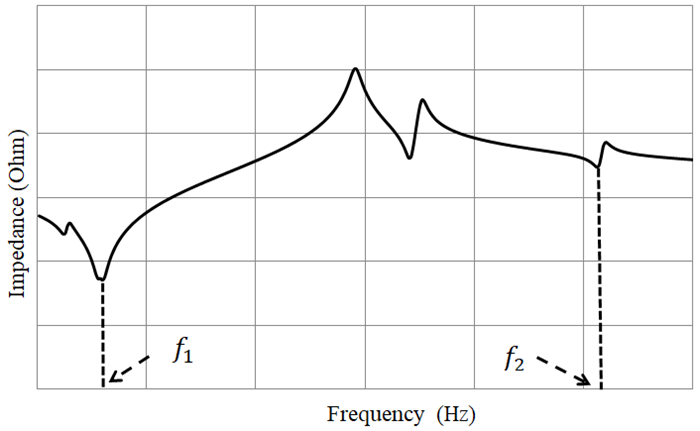
Figure 2. Impedance spectrum of the piezoelectric stator. At the primary resonance frequency, f1, the coupling element follows an inclined, narrow elliptical trajectory that generates the linear driving motion. At f2 the coupling element performs a tangential back-and-forth movement . Image Credit: PI (Physik Instrumente) LP
3.1 One Source Drive
In single-source drive mode, one of the stator’s two segmented electrodes is excited with a sinusoidal signal at the resonance frequency f1, while the second segmented electrode remains electrically open. The common electrode on the opposite surface is grounded.
Supported by a spring-damping mechanism, the stator generates a planar vibration mode at f1. This causes the coupling tip to follow an elliptical trajectory, which transfers motion to the runner (Figure 3). Reversing which segmented electrode is driven reverses the direction of motion.
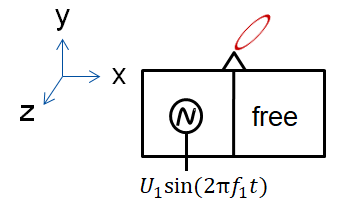
Figure 3. One source drive with PIline® stator. Image Credit: PI (Physik Instrumente) LP
One source drive enables the piezo motor to produce constant elliptical oscillations in the same vector direction.
3.2 Dual Source Dual Frequency Drive (DSDF)
Ultrasonic motors can be challenging to operate smoothly at very low speeds. Below approximately 2.0 mm/s, friction-induced vibrations may generate slow-motion noise (SMN) during piezo motor operation.
Beyond creating unwanted acoustic noise, SMN can degrade velocity stability, tracking accuracy, and overall stage performance. Its primary cause is the nonlinear transition between static and dynamic friction at the contact interface between the stator and runner.
To reduce SMN and improve low-speed tracking, PI developed the Dual-Source, Dual-Frequency (DSDF) drive method. By stabilizing the frictional interaction at the stator-runner contact points, DSDF improves low-speed controllability, suppresses vibration, and enables smaller, smoother incremental motion.
With DSDF drive, the stator is excited simultaneously in two eigenmodes that combine to produce a mixed oscillation. The coupling element’s motion therefore contains two sinusoidal components, generated by separate voltage amplitudes, U1 and U2, at the corresponding operating frequencies, f1 and f2.
As a result, the direction of motion varies continuously over time. The difference between the two eigenfrequencies is determined primarily by the geometry and mass of the piezoelectric element and typically lies outside the audible range.
Ideally, the frequency difference, f2 − f1 , is matched to the digital controller’s servo frequency, synchronizing the mixed oscillation with the closed-loop motion-control system. Figure 4 shows the resulting modulated motion of the coupling tip.
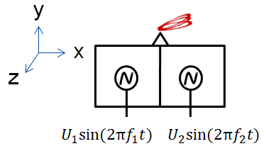
Figure 4. DSDF drive with PIline® stator. Image Credit: PI (Physik Instrumente) LP
The second drive signal produces motion of the coupling element primarily in the tangential direction while maintaining an essentially constant displacement along the y-axis. Superimposing this motion on the primary elliptical oscillation creates the modulated trajectory of the friction coupling element.
By driving the stator simultaneously with two sources at two frequencies, multiple resonance modes are excited within the piezoelectric body.
The first two vibration modes are excited at the stator’s primary operating frequency. When the difference between f1 and f2 is synchronized with the closed-loop servo frequency, the resulting force applied to the runner along the x axis follows the modulation of the two superimposed sinusoidal signals.
Download the full article now to learn more