Engineering, producing, and managing a high-precision gantry positioning system is a complicated, multidisciplinary task that demands expertise in structural mechanics, thermal modeling, mechatronics, and advanced motion control.
Multi-axis gantry platforms play a crucial role in high-throughput automation across sectors such as semiconductor inspection, laser processing, and advanced metrology. However, the challenges involved in making them accurate, dependable, and fabrication-ready are frequently underestimated.
Initially, a precision XYZ gantry may appear to be a straightforward Cartesian robot configuration – just a few stacked axes over a work area. Yet, when requirements demand nanometer resolution, micron-level repeatability, and continuous 24/7 operation, the engineering complexity escalates significantly. Below are the key challenges that make expert, system-level design crucial.
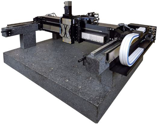
A-351 X-Y-Z gantries (Cartesian robots) come in various sizes, base materials, bearings, and motor options. Common in high-precision 3D printing, they offer advanced gantry control with coordinated multi-axis laser triggering on virtual axes. For particle-sensitive environments, low-contamination cable management solutions are available. Image Credit: PI (Physik Instrumente) LP
1. Gantry Motion Control and Dual-Drive
Synchronization – Mitigating Racking:
In dual-drive gantry bridges, even micron-level structural asymmetries or minor phase offsets between drive axes can lead to racking–a torsional deflection of the bridge around its vertical axis.
This angular distortion creates cross-axis positional errors across the work envelope, compromising process reliability. Advanced motion controllers address this by employing electronic gantry alignment loops, torque-following control, and instantaneous error correction.
However, achieving optimal outcomes requires accurate mechanical alignment, matched drive dynamics, and careful control parameter tuning. Dual-drive synchronization is as much a mechanical engineering problem as a controls engineering issue, requiring an integrated strategy from design through commissioning.
XYZ-Theta Gantry Control & Input Shaping—Advanced Algorithms, Multi-Axis Control in Automation | PI
Demonstration of advanced gantry motion control algorithms adding an extra rotational degree of freedom (when supported by the mechanical design), with the ability to enable or lock both linear and rotary axes. Video Credit: PI (Physik Instrumente) LP
2. Thermal Drift – The Silent Precision Killer
A few degrees of thermal variation are insignificant in traditional automation. However, in precision gantry systems, differential thermal expansion over extended travel axes can cause substantial positional error and, in severe cases, produce over-constrained conditions that result in mechanical binding.
More frequently, thermal growth pushes bearing preload past design limits, accelerating wear and shortening service life. Successfully mitigating this requires skill in thermal decoupling techniques, compliant structural interfaces, and material selection to control expansion paths – maintaining both precision and mechanical integrity over time.
3. High-Mass, High-Speed Gantry Dynamics – Managing Inertia for Stability
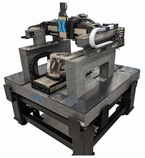
A custom granite-based A-351 gantry system with an additional long-travel linear axis and 6- DOF hexapod. Image Credit: PI (Physik Instrumente) LP
Large payloads and long-span gantry bridges in high-speed motion demonstrate substantial translational inertia. This inertia further increases control challenges, frequently resulting in overshoot, prolonged settling times, structural vibration, and reduction in constant-velocity performance. In precision manufacturing and metrology processes, where even subtle variations in speed can cause measurable process error, such deviations cannot be accepted. Achieving stable, consistent motion requires:
- Structural Stiffness and Margin – Designing for dynamic loads with ample safety factor to prevent structural mode excitation.
- Load-Path Symmetry – Maintaining balanced mass distribution to prevent cross-axis deflection and torque imbalance.
- Dynamic Disturbance Management – Accounting for real-world effects including cable drag forces, shifting payload centers of gravity, and non-ideal floor vibration conditions.
Sophisticated motion algorithms such as PILOT improve performance by effectively increasing the system’s motor constant. This allows for greater acceleration and velocity with minimized RMS current, reducing thermal load while maintaining control authority. The outcome is a gantry that can deliver consistent, production-grade precision, even under high dynamic stress and adverse operating conditions.
4. Engineering for Span-Wide Stability
As gantry bridge spans lengthen, they become increasingly susceptible to deflection under load. Achieving high stiffness without adding excessive mass requires finely tuned structural optimization. Extra weight increases inertia and degrades dynamic performance, while inadequate mass compromises rigidity and undermines positional accuracy. To address this, companies such as PI utilize sophisticated finite element analysis (FEA) along with decades of application-specific expertise to optimize structural geometry and material distribution – maximizing rigidity while maintaining dynamic responsiveness.
5. Assembly Tolerances – Precision Starts at the Frame
A gantry system’s performance relies as much on assembly execution as it does on design intent. All structural interfaces–including mounting plates, bearing rails, drive components–must satisfy strict specifications for flatness, orthogonality, and coplanarity. Mating surface deviations of even sub-100 μm can result in cumulative geometric errors, leading to binding, increased servo effort, and compromised positioning accuracy across the work envelope.
High-accuracy gantry manufacturing requires:
- Precision Machining – Tight geometric tolerances on all load-bearing and reference surfaces.
- Controlled Assembly Procedures – Fixturing and gauging to guarantee datum alignment without iterative trial-and-error.
- Stable Reference Frame – A thermally stable, rigid base structure that preserves alignment integrity under load and environmental fluctuations. Iterative alignment is unscalable in volume production and introduces unacceptable variability.
Precision must be engineered and integrated into the system, starting with the frame as the principal geometric reference. This enables downstream components to be installed to nominal position without requiring excessive adjustment.
6. Position-Based Event Synchronization – Encoder-Locked Process Timing
In processes requiring high precision, including laser pulse triggering, high-resolution image capture, or component placement, events must be initiated according to the actual physical position of the moving axis rather than the commanded position.
Across extended travel ranges, variables such as dynamic following error, servo loop latency, structural compliance, and communication delays can cause commanded-position triggers to deviate from the true encoder position, resulting in motion blur, dimensional inaccuracy, or misaligned part placement.
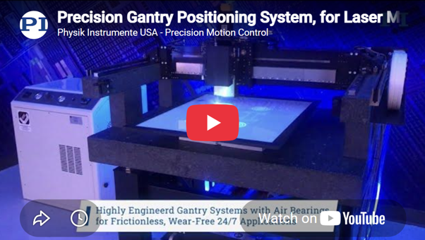
A hybrid air bearing / mechanical bearing gantry for laser processing and 3D printing. Video Credit: PI (Physik Instrumente) LP
Robust synchronization requires:
- Direct Hardware Timing – Deterministic I/O outputs triggered from the encoder’s real-time position signal, bypassing software-layer latency.
- High-Bandwidth Feedback Loops – Reducing following error under high-dynamic loads.
- Mechanical Stability – Minimizing flexure and structural lag that can offset actual tool-center-point (TCP) location from encoder reference.
A hardware-locking process triggers encoder feedback, and positional events occur with sub-microsecond determinism. This keeps motion and process execution in perfect sync–even in high-velocity, large-travel gantry applications. Novel solutions now make it possible to generate A/B quadrature signals from motion platforms without inherent digital feedback.
7. Cable Management – The Overlooked Dynamic Load Path
Cable and hose routing is frequently overlooked as a performance factor in precision gantry systems. In practice, drag chains and umbilicals generate parasitic forces, torsional moments, and varying inertial loads that can impair repeatability, reduce constant-velocity performance, and destabilize servo tuning–particularly in high-acceleration, long-travel applications. Since these forces are nonlinear, position-dependent, and challenging to model, effective design relies heavily on empirical expertise.
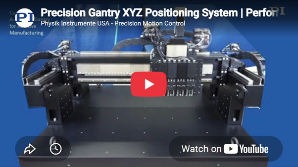
A custom 7-axis gantry for 3D printing. The Z-axis carries 4 additional motorized stages. Video Credit: PI (Physik Instrumente) LP
Key engineering considerations include:
Force Minimization – Reducing side-load and torsional input by optimizing bend radius, routing geometry, and support points.
- Dynamic Compensation – Integrating a secondary motorized cable carrier in critical applications to offload drag forces from the primary motion axis.
- Environment-Specific Solutions – Adopting low-particulate, cleanroom-rated cable management for contamination-sensitive environments.
- Predictive Integration – Considering cable-induced forces during the servo tuning and structural stiffness budgeting phases instead of after installation.
Expert cable management converts a source of instability into a controlled and predictable element of the system’s dynamic behavior. This often distinguishes a merely functional gantry from one capable of delivering repeatable, production-grade accuracy.
The Bottom Line – A Precision Gantry is a System, Not a Parts List
It is essential to recognize that error tolerances are measured in microns, whereas the number of interacting failure modes is extensive. Inertia, compliance, thermal drift, servo instability, racking, cable forces, and process timing errors can each compromise performance, often compounding in ways that are difficult to anticipate without experience.
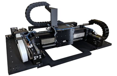
Custom, low-profile gantry with aluminum base. Image Credit: PI (Physik Instrumente) LP
While premium components are an important part of accuracy, achieving true production-grade precision requires comprehensive system engineering–a deep integration of:
- Mechanical architecture with high stiffness and low mass where needed
- Thermal behavior modeling to guarantee geometric stability under load
- Advanced control algorithms tuned to the exact mechanical dynamics
- Cable and service routing engineered to reduce parasitic forces
- Process-variable management for consistent performance under real-world conditions
The best determinant of success is collaborating with a vendor that combines decades of field-proven application experience with simulation-driven mechanical and control design, and provides completely integrated motion subsystems. PI’s precision gantry platforms are designed to satisfy requirements from initial deployment and maintain that performance long-term in challenging manufacturing environments.

This information has been sourced, reviewed and adapted from materials provided by PI (Physik Instrumente) LP.
For more information on this source, please visit PI (Physik Instrumente) LP.