To reduce friction and repair wear-related damage, nearly a quarter of global energy consumption is used.1 Thus, reducing friction can have significant positive effects on the environment and the economy. Materials with micro- to nanoscale dimensions, such as nanoparticles, nanotextured surfaces, and ultrathin boundary lubricants, have helped get closer to this objective.
On these length scales, many fundamental tribology concepts are still not entirely understood. Due to the higher surface-to-volume ratios in this regime, adhesion, viscous drag, and even atomic effects all contribute more and more, which can have a considerable impact on behavior.
The atomic force microscope (AFM), which studies tribology at the atomic to mesoscales, is indispensable due to its exceptional force sensitivity and high spatial resolution.2, 3 With an emphasis on biomedical devices and micro/nanoelectromechanical systems (MEMS/NEMS), this article reviews the advantages and benefits of current AFMs for nanotribological characterization.
How the AFM Measures Friction
The main technique used in nanotribology experiments is lateral force microscopy (LFM), also known as friction force microscopy (FFM).4 In LFM, the sample is in contact with the tip while a standard load is applied. The photodiode detector’s lateral deflection signal is watched while the cantilever is scanned perpendicular to its long axis. The tip-sample frictional force is indicated by hysteresis between the trace and retrace signals.
Images of the spatial variation in lateral forces with contrast pertaining to the materials composition are produced by raster scanning with LFM (Figure 1).
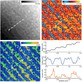
Figure 1. Imaging compositional contrast with LFM. The sample was an epitaxial film of LMSO (La0.7Sr0.3MnO3, ~18 nm thick) on an atomically flat, TiO2-terminated STO (SrTiO3) substrate. Images show topography (upper left), LFM friction (upper right), and current (lower left) obtained with conductive AFM, with sections corresponding to the dashed lines. Terraces with irregular edges and alternating high and low current are observed, suggesting alternating La1−xSrx O- and MnO2- terminated surfaces. This is confirmed by the LFM image, where low and high friction indicates differences in chemical termination from one terrace to the next. Scan size 3 μm; acquired on the MFP-3D AFM. Adapted from Ref. 5. Image Credit: Asylum Research - An Oxford Instruments Company
Conversely, from a single line scan, friction loops of the lateral force versus sliding distance can be obtained (Figure 2). The slope of the frictional force versus the applied normal load is used to calculate local coefficients of friction.
LFM signal voltages should be transformed to absolute force values to perform quantitative measurements. This entails calibrating the sensitivities of the horizontal and vertical deflections as well as the lateral and flexural spring constants of the cantilever. Although many LFM calibration protocols have been created,6–8 they are usually not a standard component of commercial AFMs.
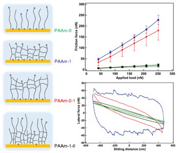
Figure 2. Characterizing friction of layered polymer films. Twolayer films of polyacrylamide (PAAm) on silicon were created with either a brush supporting a crosslinked brush-hydrogel (“gel”) or a gel supporting a brush. LFM experiments were performed with a colloidal probe in water with different film configurations: pure brush (PAAm-0), pure gel (PAAm-1), brush-gel (PAAm-0-1), and gel-brush (PAAm-1-0). The top graph shows friction force versus applied load and the bottom graph contains friction loops, with curves color-coded to film type. Although the films displayed different tribological behavior, the response was always determined primarily by the structure of the film’s outer layer where the sliding occurred. Acquired on the MFP-3D AFM with the Closed Fluid Cell. Adapted from Ref. 9. Image Credit: Asylum Research - An Oxford Instruments Company
Engineering Biomedical Interfaces
Numerous factors affect how well biomedical devices function due to tribological behavior. For example, corrosion in wet environments can cause metal implants to wear out, and friction from blood flow can damage vascular grafts. To customize the surface tribological properties of biomedical devices, research has been done to create coatings and surface treatments.
Soft polymers like hydrogels and brush structures are especially promising for this. These materials are appealing for boundary layer lubrication, targeted drug release, and other applications due to their ability to be tuned for properties like adhesion and wettability.
Figure 2 demonstrates how the above-discussed LFM concepts can be used to characterize the micro- and nanotribology of biomedical coatings. Additionally, it shows the effectiveness of colloidal probes for tribological analyses of soft materials. Tipless cantilevers with a microscale bead (typically silica) fastened for contacting the sample make up colloidal probes.
By lowering the contact stress and providing a clearly defined tip-sample contact, their larger contact area helps prevent any sample damage. By using various bead materials or functionalizing the beads (or the tips themselves) with coatings or chemical treatments, it is possible to study the relationship between surface chemistry and tribological response (depositing gold, silanization).
Additional information may be obtained by measuring different nanomechanical properties (Figure 3). Adhesion in particular is closely related to friction and has a significant impact on the tip-sample contact area, whereas modulus has an impact on lateral and normal deformation.
Force curve techniques, which can be acquired individually or in arrays, are frequently used in AFM measurements of local adhesion and modulus. Recently, new modes have been developed that allow for the swift and delicate mapping of elastic and viscoelastic moduli.
Figure 3 also demonstrates how environmental factors like temperature, relative humidity (RH), and solvent can have a significant impact on tribological properties. In fact, this dependence may be the key to fine-tuning performance in applications ranging from contact lenses to drug delivery.
Because of this, it is crucial to be able to carry out experiments in real-world settings. AFM environmental control capabilities have undergone numerous advancements, including sealed cells to regulate the gas or liquid surrounding the sample and tip. For stable, accurate temperature control from below room temperature to several hundred degrees, highly specialized sample stages are also available.
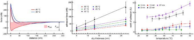
Figure 3. Evaluating adhesion in thermoresponsive polymers. Layers of end-grafted poly(di(ethylene glycol)methyl ether methacrylate) (PDEGMA) homopolymer brushes were prepared with different dry thickness d. (left) Examples of force-displacement curves acquired with a colloidal probe in water at different temperatures (d = 27 nm), indicating the adhesion force Fadh and work of adhesion wadh. (middle) Fadh increased linearly with d and monotonically with temperature. (right) wadh showed a sigmoidal temperature dependence, as did elastic modulus (not shown). The results indicate a thickness-dependent characteristic temperature at which layer properties change significantly. This tunable, thermally-induced switching could be used for nonfouling coatings and other biomedical applications. Acquired on the MFP-3D AFM with the BioHeater sample stage. Adapted from Ref. 10. Image Credit: Asylum Research - An Oxford Instruments Company
Reducing Friction in MEMS/NEMS
The influence of shrinking length scales on tribological properties is eloquently demonstrated by the emerging nanotechnology of MEMS/NEMS. Without overcoming the dramatically increased friction, stiction, and adhesion of nanoscale surfaces that slide in contact, the enormous potential of these tiny machines cannot be realized.
Two-dimensional (2D) materials like graphene are intriguing possibilities for developing new, nano-thin lubrication techniques to counteract these harmful effects. Due to weak interlayer coupling, 2D materials exhibit reduced friction, similar to three-dimensional solid lubricants.
Additionally, surfaces with misaligned or incommensurate lattices show superlubricity, in which sliding friction and stiction become so small that they appear to vanish. Figure 4 illustrates how LFM techniques enable nanoscale studies of superlubricity and other frictional impacts in few- and single-layered 2D materials.
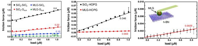
Figure 4. Demonstrating microscale superlubricity. Coefficients of friction were measured for microspheres of bare silica (SiO2) and multilayer-graphene-coated SiO2 (MLG) sliding on different surfaces (see inset in graph on right): (left) SiO2 and CVD-grown transferred graphene (Gsub), (middle) highly oriented pyrolytic graphite (HOPG), and (right) MLG sphere on hexagonal boron nitride (h-BN). Note the large differences in magnitude between different sphere-surface combinations. The ultra-low coefficients for MLG on HOPG and h-BN indicate superlubricious behavior, suggesting graphene coating as a strategy for reducing friction in MEMS/NEMS and other shaped parts. Acquired on the MFP-3D AFM. Adapted from Ref. 11. Image Credit: Asylum Research - An Oxford Instruments Company
Additionally, LFM measurements can now be made with even higher spatial resolution—to the atomic level—thanks to the atomic flatness of 2D materials. Atomic-level studies on 2D materials have been carried out since the AFM was first invented;12 the outcomes frequently diverge from their macroscale counterparts.
Stick slip, a phenomenon where lateral forces display a sawtooth pattern while scanning across a crystal lattice, is a significant illustration (Figure 5). Stick-slip behavior provides insight into basic dynamic processes like energy storage and release and can produce images of lattice-scale structures with astounding resolution (the true tip-sample contact area is typically much larger, ~100 nm2.)
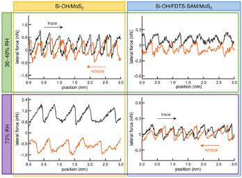
Figure 5. Investigating stick slip of 2D materials. Lateral forces on a molybdenum disulfide (MoS2) nanosheet were measured with two tips: (left) Si-OH tip created by treating a silicon tip with oxygen plasma for 1 min and (right) Si-OH tip coated with a self-assembled monolayer (SAM) of FDTS (1H,1H,2H,2H-perfluorodecyltrichlorosilane). Results are shown at (top) ambient humidity (30–40% relative humidity, RH) and (bottom) 73% RH. Adding the hydrophobic SAM decreases the already low forces observed with the bare tip and means the forces do not increase with humidity. The stick-slip behavior was understood by modeling the competing contributions of load and adhesion in each system. Acquired on the MFP-3D AFM. Adapted from Ref. 13. Image Credit: Asylum Research - An Oxford Instruments Company
Understanding how friction in these materials varies with sliding velocity, humidity, and other operating conditions is also necessary for MEMS/NEMS lubrication with 2D materials (Figure 6). LFM measurements are currently possible with “fast-scanning” AFMs at speeds between ~1 nm/second to 100 μm/second).
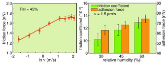
Figure 6. Exploring velocity and humidity effects. LFM experiments were performed with a silicon tip on a single layer of tungsten disulfide (WS2, thickness 5 nm) as the scan velocity v and relative humidity RH were varied. (left) The friction force increased logarithmically with v (to ~3.1 μm/s at 45% RH) and then became approximately constant. The behavior can be explained with a model that includes energy dissipation via stick slip at high velocities. (right) Both friction coefficient and adhesion force increased linearly with RH, consistent with the presence of an adsorbed water monolayer whose thickness increases with RH. Acquired on the Cypher AFM. Adapted from Ref. 14. Image Credit: Asylum Research - An Oxford Instruments Company
New video-rate AFMs offer even faster scanning (~10-100×), edging closer to real MEMS/NEMS operating speeds (up to ~10-1000 cm/s) and the hydrodynamic regime. Performance can also be assessed under realistic circumstances thanks to AFM environmental control capabilities.
These experiments call for extremely precise and repeatable lateral (XY) positioning of the AFM from an instrumentation perspective. AFMs that are more recent operate in closed-loop control, which reduces measurement artifacts and is more precise than older AFMs that operate in open-loop control.
The vertical (Z) noise floor of the AFM, which is governed by mechanical vibrations and electronic noise, has an impact on friction measurements as well. Modern AFMs can resolve extremely small force differences for applied forces ranging from piconewtons to micronewtons, with noise floors as low as 5–10 pm in many laboratories.
Summary
Numerous applications, including MEMS/NEMS and biomedical devices, would profit from a better comprehension of nanoscale friction and wear. The excellent force sensitivity, high spatial resolution, and quick scanning of today’s AFMs make them useful tribology tools. Flexible environmental control, easier setup, and other advanced features add even more power.
Acknowledgments
The authors would like to thank S. Liu, T. Ma, C. Ocal, Y. Peng, H. Schönherr, N. Spencer, D. Wesner, and X. Zheng for their assistance with the preparation of the figures. The MEMS gear image is courtesy of Sandia National Laboratories, SUMMiT™ Technologies, https://www.sandia.gov/.
References
- K. Holmberg and A. Erdemir, Friction 5, 263 (2017).
- R. Carpick and M. Salmeron, Chem. Rev. 97, 1163 (1997).
- Nanotribology and Nanomechanics (4th edition), ed. B. Bhushan (Springer-Verlag, Berlin, 2017).
- R. Bennewitz, “Friction Force Microscopy,” in Fundamentals of Friction and Wear on the Nanoscale, eds. E. Gnecco and E. Meyer (Springer, Berlin, 2015), Ch. 1.
- L. López-Mir, L. Balcells, S. Valencia, F. Kronast, B. Martínez, J. J. de Miguel, and C. Ocal, Cryst. Growth Des. 16, 5479 (2016).
- D. Ogletree, R. Carpick, and M. Salmeron, Rev. Sci. Instrum. 67, 3298 (1996).
- M. Munz, J. Phys. D: Appl. Phys. 43, 063001 (2010).
- A. Labuda, C. Cao, T. Walsh, J. Meinhold, R. Proksch, Y. Sun, and T. Filleter, “Static and dynamic calibration of torsional spring constants of cantilevers,” Rev. Sci. Instrum. 89, 093701 (2018).
- A. Li, S. N. Ramakrishna, P. C. Nalam, E. M. Benetti, and N. D. Spencer, Adv. Mater. Interfaces 1, 1300007 (2014).
- E. Wassel, D. Wesner, and H. Schönherr, Eur. Polym. J. 89, 440 (2017).
- S.-W. Liu, H.-P. Wang, Q. Xu, T.-B. Ma, G. Yu, C. Zhang, D. Geng, Z. Yu, S. Zhang, W. Wang, Y.-Z. Hu, H. Wang, and J. Luo, Nature Commun. 8, 14029 (2017).
- C. Mate, G. McClelland, R. Erlandsson, and S. Chiang, Phys. Rev. Lett. 59, 1942 (1986).
- X. Cao, X. Gan, Y. Peng, Y. Wang, X. Zeng, H. Lang, J. Deng, and K. Zou, Nanoscale 10, 378 (2018).
- D. Feng, J. Peng, S. Liu, X. Zheng, X. Yan, and W. He, Mater. Res. Express 5, 015026 (2018).

This information has been sourced, reviewed and adapted from materials provided by Asylum Research - An Oxford Instruments Company.
For more information on this source, please visit Asylum Research - An Oxford Instruments Company.