Magnetic force microscopy (MFM) is a specialized form of atomic force microscopy (AFM) that achieves high sensitivity and spatial resolution for mapping magnetic field distributions on surfaces. MFM is applicable across diverse fields such as materials science, magnetism, data storage, and life sciences.
This article highlights the advantages of substituting the initial TappingMode™ topographic scan in MFM with a PeakForce Tapping® scan.
MFM and PeakForce Tapping
In MFM, a magnetic-coated AFM probe interacts with magnetic field gradients from the sample, causing detectable forces on the probe's cantilever. To focus on magnetic interactions, MFM is often performed using a two-pass method called LiftMode™, introduced by Bruker two decades ago.
During the first pass, the AFM typically operates in TappingMode to capture a topographic image. In the second pass, the tip is lifted to a constant height to measure the magnetic force gradient by analyzing the cantilever's amplitude and phase near its resonance frequency. This lift scan minimizes van der Waals interactions, allowing for more precise separation of topographic and magnetic signals.
![(a) Schematic of LiftMode, showing first pass for height and second pass at lift height for magnetic data. (b) Height and (c) phase channels using PeakForce MFM on a perpendicular magnetization multilayer [Pt/Co/Pt]x25. Topography acquired during main scan and phase of the oscillating cantilever (representing magnetic domains) acquired during lift scan. Scan size 2x2 µm. Sample courtesy K. Bouzehouane, Université Paris-Saclay, Thales](https://www.azonano.com/images/Article_Images/ImageForArticle_6884_17472867612584088.png)
Figure 1. (a) Schematic of LiftMode, showing first pass for height and second pass at lift height for magnetic data. (b) Height and (c) phase channels using PeakForce MFM on a perpendicular magnetization multilayer [Pt/Co/Pt]x25. Topography acquired during main scan and phase of the oscillating cantilever (representing magnetic domains) acquired during lift scan. Scan size 2x2 μm. Sample courtesy K. Bouzehouane, Université Paris-Saclay, Thales. Image Credit: Bruker Nano Surfaces and Metrology
Bruker’s PeakForce TappingMode has become the preferred choice for many topographic applications due to its direct force control and capability to function at lower forces. These features enhance spatial resolution, allow imaging of delicate samples, and extend the lifespan of the tips. Moreover, PeakForce Tapping facilitates the simultaneous gathering of quantitative data on mechanical properties like adhesion and modulus.
Another advantage of PeakForce Tapping is the inclusion of Bruker’s ScanAsyst® routines, which automatically optimize key feedback parameters for user-friendly operation and deliver high performance regardless of the operator's experience level.1 ScanAsyst was utilized for all images in this discussion.
Combining PeakForce Tapping with MFM enables the correlation of magnetic and mechanical properties, as illustrated in a case study involving a 20 TB hard disk drive. Adding ferrofluid drops on the disk created noticeable differences in adhesion and magnetic fields, with 1x1 μm images showcasing high spatial resolution, resolving features smaller than 30 nm.
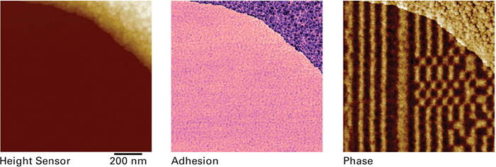
Figure 2. 20 TB HDD intentionally covered with some ferrofluidic drops in the top right corner. Topography and adhesion were acquired during the main scan, and phase of the oscillating cantilever (representing the magnetic domains) was acquired during the LiftMode scan. Scan size: 1x1 μm, lift height: 8 nm, oscillation amplitude: 10 nm. Sample courtesy S. Montoya, University of California San Diego. Image Credit: Bruker Nano Surfaces and Metrology
When PeakForce Tapping is applied in Kelvin probe force microscopy (KPFM) and electric field microscopy (EFM), similar enhancements are observed. Bruker’s PeakForce KPFM™ modes are well-established and routinely used.2
Probe Optimization for PeakForce MFM
PeakForce Tapping can be used with a variety of cantilevers, as its functioning is independent of the cantilever's resonance behavior. The choice of probes is crucial for quality MFM measurements, making the flexibility offered by PeakForce Tapping a significant advantage.
MFM relies on detecting phase or frequency shifts in an oscillating cantilever while scanning at a fixed height. Sensitivity to these shifts correlates directly with the cantilever’s quality factor and detection frequency, and inversely with the spring constant. Thus, lowering the spring constant while enhancing the quality factor and resonance frequency is essential for improved sensitivity.3
The design of our innovative PeakForce MFM probes emphasizes a reduced spring constant, allowing operation at lower force levels. This was achieved by decreasing the cantilever's thickness and width and adopting a paddle shape for compatibility with standard laser spot sizes.
These design modifications resulted in substantial improvements in MFM sensitivity, achieving a threefold increase in phase sensitivity and a twelvefold increase in frequency sensitivity. This advancement enables lower oscillation amplitudes and reduced lift heights, enhancing spatial resolution and throughput.
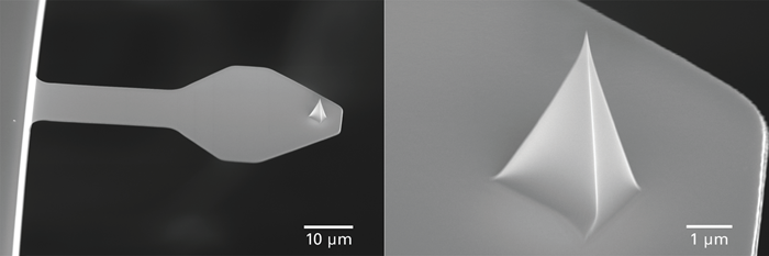
Figure 3. PFMFM-LM probe with nominal spring constant of 0.4 N/m, and resonance frequency of 130 kHz. Cantilever has a length of 60 μm and has a paddle-shaped profile. Image Credit: Bruker Nano Surfaces and Metrology
Changes in probe geometry also allowed for using thinner magnetic coatings with lower magnetic moments. Lower-moment coatings generally yield weaker signals, requiring higher sensitivity for acceptable signal-to-noise ratios. Thinner coatings enhance spatial resolution and minimize tip-induced magnetization changes. A new optimized process was developed to reduce stress-induced bending of the cantilever.
![Perpendicular magnetization multilayer [Pt/Co/Pt]x5 domain walls. (a) MFM phase image (scan size 3x3 µm) and (b) phase data across the interface shows high sensitivity and spatial resolution. (c) Adhesion image co-localized with phase and (d) height images showcases the powerful capability of PeakForce MFM to additionally analyze mechanical properties. Sample courtesy K. Bouzehouane, Université Paris-Saclay, Thales](https://www.azonano.com/images/Article_Images/ImageForArticle_6884_17472879618763649.png)
Figure 4. Perpendicular magnetization multilayer [Pt/Co/Pt]x5 domain walls. (a) MFM phase image (scan size 3x3 μm) and (b) phase data across the interface shows high sensitivity and spatial resolution. (c) Adhesion image co-localized with phase and (d) height images showcases the powerful capability of PeakForce MFM to additionally analyze mechanical properties. Sample courtesy K. Bouzehouane, Université Paris-Saclay, Thales. Image Credit: Bruker Nano Surfaces and Metrology
MFM Combined with Torsional Resonance
In conventional and PeakForce MFM, the cantilever oscillates vertically, but this can be replaced by a horizontal oscillation, creating a torsional mode known as TR-MFM.4 In TR-MFM, the tip detects the magnetic field with a force gradient parallel to it.
This method measures in-plane force gradient components with the exact resolution and signal-to-noise ratio as traditional modes.
Research on TR-MFM for imaging magnetic structures indicates its capability to achieve magnetic contrast without topographic interference and a 15% enhancement in lateral resolution due to reduced tip-sample separation.
![PeakForce MFM with vertical (left in image pairs) and lateral (right in image pairs) magnetic domain imaging. A torsional resonance was applied during the lift scan to acquire the lateral field images. In (a), the probe was oriented at 0°. Upon rotating the sample 90°, the vertical field remains the same, but the lateral field rotates. Tip oscillation direction is indicated beneath each image. Scan size 3.8x3.8 µm. Sample: perpendicular magnetization multilayer [Pt/Co/Pt]x25, courtesy K. Bouzehouane, Université Paris-Saclay](https://www.azonano.com/images/Article_Images/ImageForArticle_6884_1747287968464383.png)
Figure 5. PeakForce MFM with vertical (left in image pairs) and lateral (right in image pairs) magnetic domain imaging. A torsional resonance was applied during the lift scan to acquire the lateral field images. In (a), the probe was oriented at 0°. Upon rotating the sample 90°, the vertical field remains the same, but the lateral field rotates. Tip oscillation direction is indicated beneath each image. Scan size 3.8x3.8 μm. Sample: perpendicular magnetization multilayer [Pt/Co/Pt]x25, courtesy K. Bouzehouane, Université Paris-Saclay, Thales. Image Credit: Bruker Nano Surfaces and Metrology
Measuring components of the force gradient provides deeper insights into the source of the force and its gradient.
An example illustrating this is shown, where both vertical and lateral magnetic fields are measured in PeakForce MFM, revealing directional influences not seen in the vertical field alone.
PeakForce Tapping Enhances Magnetic Force Microscopy
Integrating PeakForce Tapping with MFM marks a notable advancement in high-resolution magnetic imaging. By utilizing PeakForce Tapping instead of TappingMode for the initial scan, researchers can achieve improved spatial resolution, heightened sensitivity, and better imaging of fragile samples.
The new PeakForce MFM probes, designed with optimized spring constants and magnetic coatings, further enhance measurement capabilities. Combining PeakForce Tapping MFM with torsional resonance techniques also improves the understanding of magnetic fields in three dimensions, providing a powerful toolkit for nanoscale magnetic property exploration.
References
- Bruker. (2025). Introduction to Bruker’s ScanAsyst and PeakForce Tapping AFM Technology - AN133 - The Nanoscale World. (online) Available at: http://nanoscaleworld.bruker-axs.com/nanoscaleworld/media/p/1548.aspx (Accessed 15 May 2025).
- PeakForce Kelvin Probe Force Microscopy. Bruker Application Note AN140.
- Kazakova, O., et al. (2019). Frontiers of magnetic force microscopy. Journal of Applied Physics, 125(6), p.060901. https://doi.org/10.1063/1.5050712.
- Bruker. (2015). Application Note: Torsional Resonance Modes. (online) Available at: https://www.bruker.com/en/products-and-solutions/microscopes/materials-afm/resource-library/an-158-torsional-resonance-modes.html (Accessed 15 May 2025).

This information has been sourced, reviewed and adapted from materials provided by Bruker Nano Surfaces and Metrology.
For more information on this source, please visit Bruker Nano Surfaces and Metrology.