PI's Fast, Multi-Channel Photonics Alignment (FMPA) technology is a collection of firmware-level commands built into the company's highest-performing digital nanopositioning and hexapod controllers.
These commands enable rapid coupling optimization between photonic and other optical devices and assemblies, including optimization for many degrees of freedom, inputs, outputs, elements, and channels. Importantly, these improvements can frequently be executed concurrently, even if the separate optimizations interact.
Devices that have seen considerable process savings using this alignment technology include multichannel silicon photonics devices such as fiber array units (FAU), LIDAR sensors, and smartphone camera assemblies.
Serial Versus Parallel Alignments
For example, in the short waveguides increasingly being used in silicon photonics (SiP) devices, the input and output couplings can steer each other. As one side is optimized, the other moves somewhat and requires re-optimization.
Previously, this required a time-consuming, serial sequence of back-and-forth adjustments of the input, followed by the output, until a worldwide consensus alignment was obtained.
Similarly, when optimizing an angle, the transverse alignment is disrupted and must be reoptimized, resulting in another time-consuming serial loop. However, with FMPA, these interacting alignments can typically be improved concurrently, or in parallel.
This enables worldwide consensus alignment to be established in one step. In many cases, tracking and continual adjustment of all alignments is possible, allowing drift, curing stresses, and other factors to be compensated for.
The end result is significantly increased manufacturing throughput and, in many cases, considerably decreased costs. This parallelism is becoming increasingly important in process economics as gadgets become more sophisticated and accurate, and their production and testing requirements become more stringent.
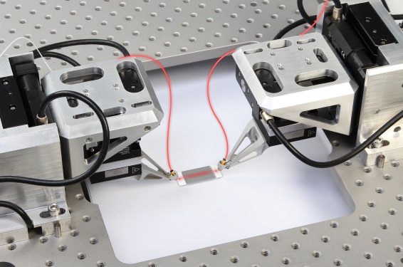
Figure 1. Aligning the inputs and outputs of waveguide devices at an industrial pace requires parallel optimization and nanoscale accuracy. Image Credit: PI (Physik Instrumente) LP
Look for the Loops
To use this capacity for greatest overall cost reductions, some different thinking may be required than what is typical of classical alignment hardware.
In general, one looks for sequential alignment loops that can typically be replaced with simultaneous improvements. This article examines a few sample applications and addresses implementation challenges to demonstrate how these remarkable new capabilities may be used to boost productivity in testing and packaging.
Background of FMPA Operation
The device alignment should be divided into discrete alignment operations. For example, probing a waveguide with one input and one output using lensed fibers usually requires four alignment processes:
- Transverse optimization routine, input
- Transverse optimization routine, output
- Z optimization routine, input (beam waist seek)
- Z optimization routine, output (beam waist seek)
Add additional inputs or outputs as needed.
- Theta-Z optimization routine, input
- Theta-Z optimization routine, output
If the device needs optimization in theta-X and theta-Y, include:
- Gimbaling optimization routine, input
- Gimbaling optimization routine, output
Dividing the entire alignment effort into several subprocesses is critical to determining which processes can be completed concurrently. With FMPA, a list of alignment routines is taken and declared directly in the controller. This should only be done once (and can be modified or amended at any time).
Once defined, a routine can be run repeatedly. Parallelism enables the execution of many routines at the same time. Defining a process involves directing the controller on which axes are involved, while analog input represents the quantity to be optimized (optical power, MTF, etc.), and the process options.
For ease, each process can be named; the numbers provided on the list above are ideal for this. Routines are started by using the ‘Fast Routine Start’ command, FRS.
Referring to the list above, FRS 1 would begin transverse optimization on the input; FRS 2 would begin the transverse optimization of the output; and FRS 1 2 would accomplish both at once.
Types of Alignment Routines
Independent active alignment engine hardware is required on each side of the device. Any number of alignment engines can be employed; the most frequent configurations use one or two, but three or more will become more popular as SiP technology advances.
Typically, each alignment engine consists of a multi-axis long-travel assembly and a shorter-travel, high-speed, high-resolution piezoelectric multi-axis nanopositioning stage. The modularity of the technique is a significant advantage.
Some applications do not require the lengthy trip mechanism, nor do they need the nanopositioning stage's speed, precision, or continuous tracking capability. In each case, regardless of the type of motion system used, all FMPA algorithms and processes are nearly the same; the only difference is the capability.
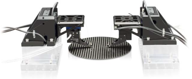
Figure 2. F-712.MA2 high precision fiber alignment system. Image Credit: PI (Physik Instrumente) LP
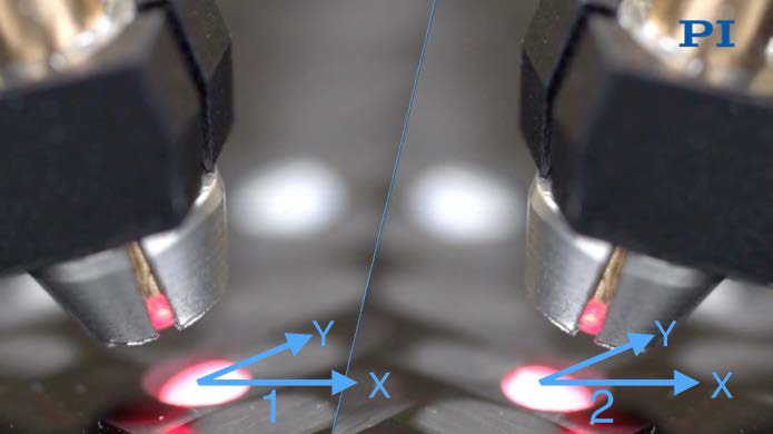
Figure 3. Dividing a task like waveguide I/O coupling into subtasks like “1” and “2” shown will illuminate opportunities for parallel execution. Here, the two processes can proceed in parallel even though they interact, especially in the case of short waveguides where inputs and outputs steer each other. Similarly, processes related geometrically (such as transverse and Z optimization in situations such as shown, with an angled beam) can be performed in parallel. Image Credit: PI (Physik Instrumente) LP
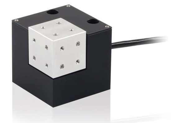
Figure 4. NanoCube®, piezo-based, high dynamic, three-axis scanner with 100 µm travel range. Besides its nanoscale resolution and blazing speeds, this flexure-based nanopositioning subsystem can perform continuous tracking without wear. Image Credit: PI (Physik Instrumente) LP
Long Travel Options
A stack of linear stages is sufficient for scenarios that do not require any angular optimizations or array alignment.
Otherwise, a hexapod six-axis motion system is required, not only in situations requiring full six-degree-of-freedom positioning and optimization, but also in simpler situations, because the hexapod allows the rotational center point of even a single angular optimization to be placed on the optical axis, at the beam waist, and so on.
This is critical for eliminating parasitic geometric errors, which are another key to increasing overall productivity.
Sometimes very lengthy motion in one or two axes is required for loading operations, in which case the hexapod can be installed on a long-travel motorized stage. (The hexapod controller can accommodate two extra DC-servomotor axes. Alternatively, force sensor elements can be included).
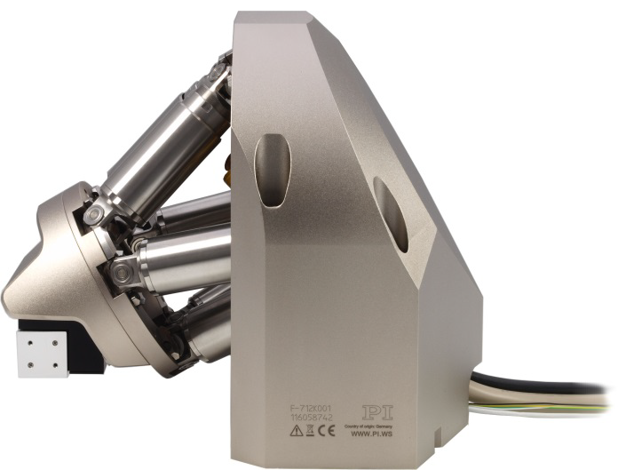
Figure 5. Single-sided fiber alignment system. Image Credit: PI (Physik Instrumente) LP
The Alignment Processes
There are two sorts of processes: areal scans, which aim to pinpoint a peak within a specific region, and gradient searches, which aim to efficiently improve coupling (and optionally follow it to reduce drift processes, disturbances, and so on).
Gradient Searches
Gradient searches cause a little circular dither motion of one device versus the other, modulating the coupling.
The amount of modulation of the figure-of-merit being optimized (for example, optical power or MTF) represents the local gradient of the coupling. At the optimum, the modulation is zero (Figure 6).
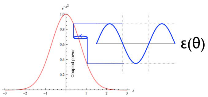
Figure 6. Graphical depiction of gradient determination via a circular dither, which modulates the coupled power (or other quantity) observed. The phase of the modulation with respect to the dither indicates the direction toward the maximum, while its amplitude falls to 0 at the optimum. Image Credit: PI (Physik Instrumente) LP
|ε(θ)|=∇I=(I_min-I_max)/I_min
Equation 1. The observed gradient serves as a measure of alignment error.
The local gradient can be quantitatively deduced from the observed modulation using a simple computation, such as Equation 1. At the optimum, the gradient ∇I equals zero. Any axes in an FMPA system can accomplish any of these alignments (according to their physical limitations, of course).
As a result, areal scans can be performed using motorized stage axes, which can be quite useful for detecting first light.
Gradient searches are most commonly associated with transverse optimization, although they can also be performed (for example) in a single linear axis, which is well-suited for localizing the beam waist in a lensed coupling, or in a gimbaling fashion to optimize an angle.
There are numerous possibilities. These are extremely versatile algorithms that can be used for a wide range of optimization tasks, including bulk optic, cavity, and pinhole alignments.
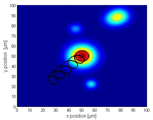
Figure 7. Optical power distribution. Image Credit: PI (Physik Instrumente) LP
FMPA is distinguished by the ability to run several gradient searches simultaneously. Transverse optimizations are typically the most delicate and impacted by other alignments. As a result, transverse procedures are typically limited to high-speed, high-resolution piezoelectric stages like PI's P-616 NanoCube.
The NanoCube's high speed and continuous tracking capacity enable transverse optimization to be maintained during Z and angular optimizations, which would otherwise necessitate a time-consuming, looping sequential approach.
Another recent advancement is the PILightning First Light Detection algorithm that can reduce time to find first light by orders of magnitude, especially in dual-sided alignment applications.
Areal Scans
Scanning an area to discover the approximate location of the highest coupling peak is beneficial for a variety of purposes:
- Seeking the first light
- Profiling a coupling to determine its dimensions: this could be a critical process control step
- Localizing the principal mode of a coupling for optimization via gradient search: this hybrid technique prevents locking onto a local maximum and is quite powerful.
FMPA controllers not only reduce the areal scan to a single command, but they also have automatic curve-fitting capabilities and a data recorder that can capture the profile on the fly for later retrieval, analysis, or databasing.
FMPA areal scans are very quick, taking about 300 milliseconds for common NanoCube applications and loads. The curve-fitting capacity can fit a Gaussian to a relatively sparse scan (i.e., a quick scan), allowing good localization of the optimal coupling point without spending a long time on a very fine scan.
It can also determine the centroid of a flat-top ("top hat") coupling, for example when probing a deposited photodetector with a single-mode fiber. This permits the scan to end with the fiber at the geometric center of a flat or inclined top-hat coupling.
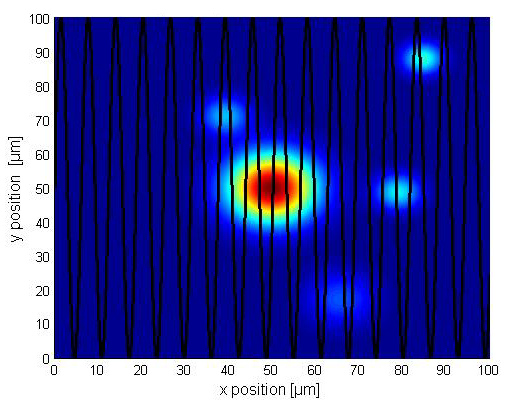
Figure 8. Optical power distribution. Image Credit: PI (Physik Instrumente) LP
FMPA offers unique areal scan possibilities, including single-frequency sinusoid and spiral scans.
These are much faster than typical raster or serpentine scans because they are genuinely continuous, eliminating the settling requirements of traditional scans' stop-and-start motions, and the frequency can be adjusted to prevent triggering structural resonances.
A constant-velocity spiral scan may also be selected, allowing data to be collected with a consistent density over the spiral.
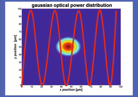
Figure 9. Sinusoidal area scan. Image Credit: PI (Physik Instrumente) LP
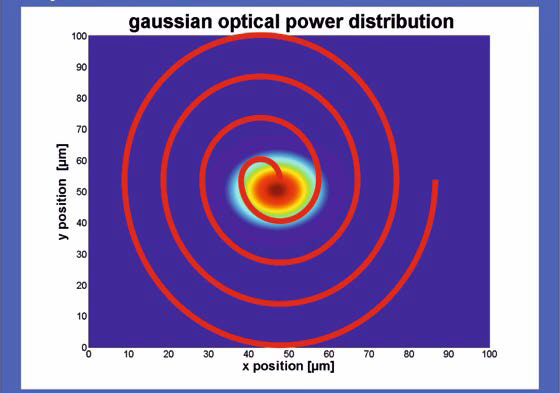
Figure 10. Spiral area scan. Image Credit: PI (Physik Instrumente) LP
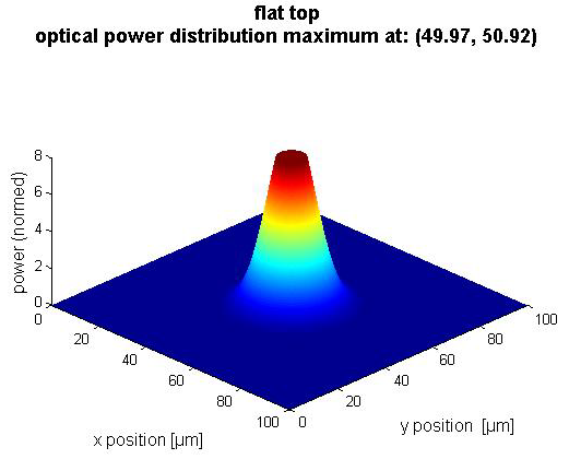
Figure 11. Uniquely, PI FMPA controllers can perform a fast areal scan and automatically calculate and align robustly to the centroid position of upright and tilted top-hat couplings. Image Credit: PI (Physik Instrumente) LP
Download the full article now to learn more