Integrated photonics is becoming increasingly important to meet the increased bandwidth and energy requirements of large language models (LLMs) and hyperscale data centers.
As existing electrical interconnects reach their performance limits, photonic integrated circuits (PICs) provide a scalable and low-power option for high-speed optical communication. With PICs increasingly being used in high-volume manufacturing, demand for precision test automation systems has increased.
Achieving consistent, sub-micron alignment under production settings defined by mechanical vibration and thermal variation necessitates advanced system design and dynamic performance management.
Precision active photonics alignment systems, such as the PINovAlign42, are vital to ensure high-yield PIC production, which directly contributes to the scalability and efficiency of next-generation AI infrastructure.
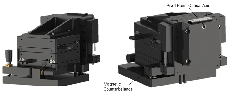
Rearward and forward-facing, oblique view of F-141 PI NovAlign Robotic Photonics Aligner. Image Credit: PI (Physik Instrumente) LP
This article investigates key strategies for ensuring alignment precision in real-world scenarios. It begins with an anatomy of photonics test automation design, then looks into the dynamics of photonics probes on a production scale.
It also investigates the effects of both direct and indirect vibration disturbances before concluding with realistic measurement methodologies and mitigation measures for ensuring stable, high-performance photonic coupling on the manufacturing floor.
After this, it explores the design of the 6DoF PINovAlign42 alignment system, designed for PIC testing, and how it maintains nanometer-level precision despite production-scale vibrations.
The article examines both direct and indirect dynamic effects, supported by real-world data and mitigation measures that maintain speed and throughput.
Designing for Precision in Motion: Important Aspects for Robotics in Photonics Test Applications
A good photonics test system must combine nanometer-level precision with high-speed dynamics in a small, low-wear package.
The PI NovAlign system does this in a 100 mm cube by providing 6DoF motion, adjustable magnetic balancing for different loads, and excellent response around the optical axis. Stability in pitch and yaw, along with built-in dampening to inhibit high-frequency resonances and eliminate axis crosstalk, assures consistent nanoscale alignment.
Key Requirements:
- Compact size (100 mm x 100 mm x 100 mm) with little probe arm reach required
- Six degrees of flexibility with low wear during high-duty-cycle repetitive motions
- Short stroke for linear and angular motion (25 mm/10 degrees)
- Supports light loads (<500 g) with adjustable magnetic counterweight
- High dynamics, particularly in higher order terms (r', r''), with accelerations up to 2g
- The optical axis roll is dynamic and responsive up to 1000 degrees per second
- The pitch and yaw are exceptionally stable, adjustable, and lockable
- Minimal position adjustment and stability at around 30 nm
- Inherent dampening of high-frequency resonances with low crosstalk
PINovAlign6 6-DOF High-Speed Photonics Alignment System - Pivot Point Demo
The video above shows the fully motorized version of the PINovAlign 6-DOF photonics alignment system in a pivot point demo. Video Credit: PI (Physik Instrumente) LP
Component Level Considerations: Linear Motor
The Halbach Array Linear Motor, the system's powerhouse, is a critical component that enables the PINovAlign's performance. The Halbach array, invented by Klaus Halbach at Lawrence Berkeley National Laboratory for use in particle accelerators, is designed to concentrate magnetic force on one side while almost completely eliminating it on the other.
This innovative magnet configuration creates a highly focused magnetic field, resulting in increased force density and motor efficiency.
This is a significant advantage in compact systems such as photonics aligners. The motor's concentrated magnetic field delivers more force in a smaller footprint, making it both strong and space-efficient, ideal for precision instruments used in limited areas.
A B-field simulation from the finite element analysis visually confirms how the magnetic field lines are tightly corralled and intensified, demonstrating the effectiveness of this configuration in delivering high dynamic performance in a small package.

Halbach Array Motor Concept and B-Field Simulation using finite element analysis. Image Credit: PI (Physik Instrumente) LP
Component Level Considerations: Glass Scale Linear Encoder
The glass scale linear encoder is a critical component of the PINovAlign system, acting as the major feedback mechanism for position control.
This encoder delivers direct, high-resolution visual feedback by sensing the stage's location at the point of load. In this setup, the glass scale is mounted on the moving carriage, while the optical read head is integrated into the stationary base, allowing for continuous, real-time displacement monitoring.
The encoder uses a 20 µm signal period with a SIN/COS analog output at 1 V peak-to-peak. When combined with 14-bit interpolation in the drive electronics, the system yields a position resolution of around 1 nm.
This degree of precision is crucial for maintaining alignment stability in photonics applications that need sub-micrometer tolerances, and it emphasizes the importance of direct metrology at the load for reducing structural deflection and measurement uncertainty.
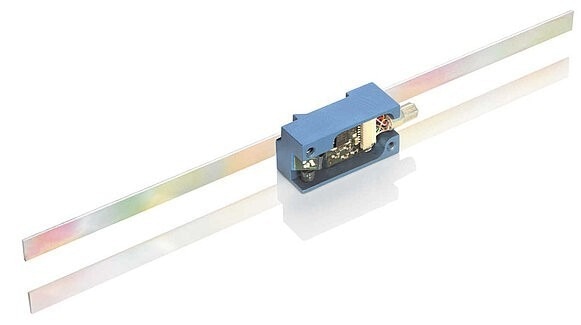
A linear encoder with optical read head. Image Credit: PI (Physik Instrumente) LP
Component Level Considerations: Body and Bearings
The PI NovAlign system's smooth, precise motion is largely due to its optimized body and bearing design. The structural frame is made of aerospace-grade anodized aluminum alloy (6061-T6), which is known for its excellent strength-to-weight ratio, fatigue resistance, and ability to retain rigidity with minimal moving mass.
These qualities are critical for nanopositioning applications that require the precise manipulation of photonics components such as fiber array units (FAUs), lensed fibers, and precision fixtures.
Motion is guided by precision-machined crossed roller bearings made of high-carbon steel. These bearings are preloaded with anti-creep and low-friction qualities, ensuring smooth, reproducible motion over the short travel distances common in photonic alignment operations. Furthermore, they are built to last and perform consistently even in the most demanding industrial scenarios.
The device achieves nanometer-level stability and reproducibility for advanced photonics testing by combining a rigid, lightweight structural body with durable bearing technology.
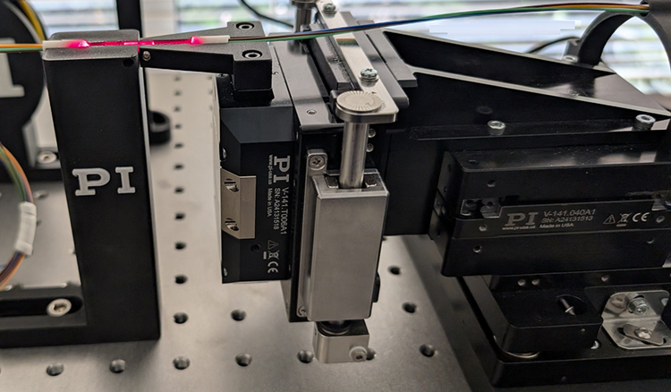
FAU alignment with the PINovAlign42. Image Credit: PI (Physik Instrumente) LP
Evaluating and Understanding Photonic Probe Dynamics Performance
To speed up signal collection during photonic alignment, the PINovAlign system uses algorithmic first-light search and signal optimization procedures powered by high-dynamic, periodic motion.
The dynamic performance of these routines is assessed based on the system's ability to retain precision throughout a range of operating frequencies.
In practice, this includes balancing injected motion dynamics with the ensuing disturbances, positional stability, and error behavior, as well as paying close attention to the search algorithm's pathing features.
Photonics FAU Alignment / 100Hz Scan with PINovAlign PIC Alignment System. Zoomed out and close-up.
100 Hz scan, close-up and full frame. Video Credit: PI (Physik Instrumente) LP
Fast Photonics Alignment: First Light Search and Complete Gradient Search with F-141 PINovAlign.
Full alignment sequence, including first-light search and gradient search. Video Credit: PI (Physik Instrumente) LP
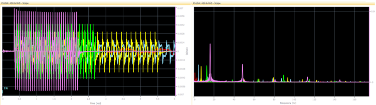
Comparative error for algorithmic signal search at different operating frequencies (tested at 1 to 40 Hz) and fast Fourier transform (FFT) of positioning error. This suggests that higher-frequency operation–while useful for speed–can begin to excite structural harmonics (in the stage, fiber holders, and surrounding components), emphasizing the importance of looking at the complete system and tuning algorithmic dynamics to match the mechanical and control limitations. Image Credit: PI (Physik Instrumente) LP
Transfer Function Characterization
Evaluating the Resonance Signatures of Precision Robotic Alignment Systems
Each mechanical system has an inherent frequency response influenced by its mechanical design, engineering decisions, and the operating environment, including the control module.
This frequency response function can be defined by selectively applying ascending frequency current excitation sweeps, but other approaches, such as white noise excitation, can also be used.
Engineers can identify critical features such as first-mode resonances, gain and phase margins, and system stability by analyzing the gain and phase relationship between the excitation signal and the system's response, also known as the open-loop transfer function.
In the absence of such an analysis, the servo responsiveness and gain parameters must be carefully calibrated to prevent instability. This often involves maintaining adequate safety margins, such as a 6 dB gain buffer and a 30 degree phase margin, to account for differences in design and environmental conditions.
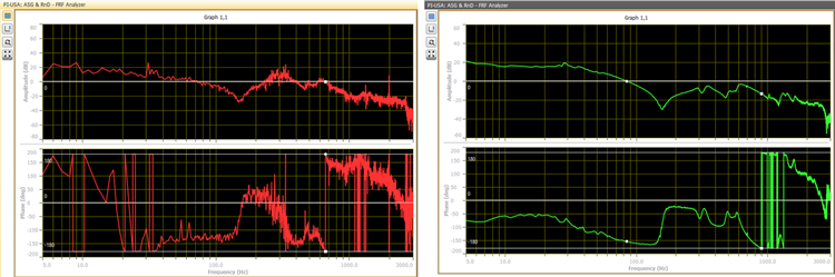
Transfer function of the X-axis prior to application of a notch filter at first-mode resonance observed at 315 Hz (left) and after the notch filter is applied to the servo with position-integral-velocity (PIV) gains optimized (right). Image Credit: PI (Physik Instrumente) LP
Indirect Vibration Disturbance Injection
Environmental Vibrations Unrelated to Direct Robotic Aligning Action
Photonic probe and test manufacturing tools are comprised of structural and peripheral components that must be designed to work with robotic photonic alignment systems while carefully balancing different limitations.
These include economic considerations, severe size and volumetric constraints, and the requirement to integrate extra sensors, equipment, and electrical probes.
The system must additionally account for physical touch or inertial influences from wafer or chip handlers and fixtures.
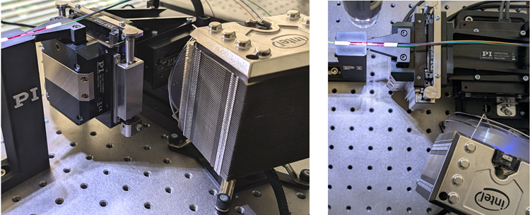
Front and top view of a forced-cooling fan coupled to a structure positioned near the PI (Physik Instrumente) LP NovAlign 42 precision robotic aligner to understand the influence of localized fan airflow on edge-coupled fiber-array coupling using a four-channel, 50 µm core MM fiber with a loopback circuit (250 µm channel spacing). Image Credit: PI (Physik Instrumente) LP
Environmental control is another key consideration. These instruments must efficiently control forced heating and cooling by combining vacuum pumps, compressors, fans, heaters, chillers, and other components.
The materials used, such as aluminum probe arms and base plates, steel welded frames, and hanging structures made of granite or aluminum, are also important in defining overall system stiffness and thermal stability.
At the same time, the equipment must be designed to work seamlessly with both robotic machine handlers and human operators, whether as part of a dedicated photonics test system or as a hybrid tool that performs additional assembly or process activities.
Importantly, the system must provide robotic alignment precision that allows for reliable optical connection with tolerances of less than 100 nanometers, even in the face of both direct and indirect disturbances. This demands a platform that is not only very dynamic but also extremely stable.
Case Study: Insertion Loss Under Forced Cooling Disturbance
To evaluate the impact of forced cooling on photonic alignment performance, a profiling experiment was conducted using a characterization algorithm with fiber-array-to-fiber-array coupling through a four-channel fiber-array unit (FAU) featuring a 50 µm core and 250 µm channel spacing in a loopback configuration.
In this arrangement, a 1 Hz X-scan algorithmic signal search was used to find the peak optical coupling position, which the system then maintained without active tracking for four seconds.
The results displayed below compare two operating conditions: with the cooling fan turned off (red trace) and on (yellow trace). The data clearly show that localized forced airflow and a structurally coupled vibration source cause observable disruptions, reducing coupling stability and increasing insertion loss.
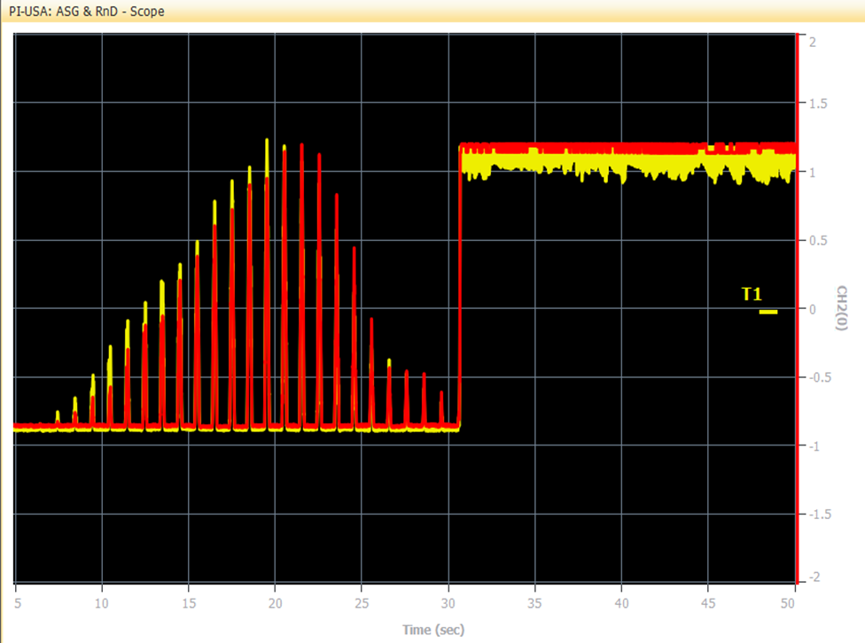
One Hz, X-Scan algorithmic signal search with move-to-peak coupling position and hold position stable (no active track). The red signal represents the fan-off state, and the yellow is the fan-on state. The impacts on coupling stability metrics and insertion loss are clearly visible. Image Credit: PI (Physik Instrumente) LP
Structurally Coupled Fan Assembly Impact on Setup
To reduce the impact of forced cooling on fiber array photonic edge coupling, elastomer interfaces were added to the structural coupling point between the fan and the robotic aligner. This method was evaluated under three distinct settings with a four-channel multimode fiber array.
The first scenario was an X-scan area signal search at 20 Hz with no fan present, which served as the baseline condition (red trace). In the second scenario, the identical scan was performed with the fan directly connected to the robotic aligner structure (yellow trace), resulting in mechanical vibrations that reduced coupling.
In the third scenario, the fan remained in place but was secured with elastomeric dampers at the structural interface (blue trace), which served to isolate the robotic platform from vibration-induced disturbances.
The findings demonstrated significant differences in normalized insertion loss and coupling stability among the three conditions. The use of elastomeric interfaces considerably minimized the detrimental effects of forced cooling, resulting in improved optical coupling performance when compared to direct structural coupling.
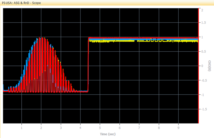
Plot showing alignment signal characteristics using fixed-frequency algorithmic signal search on the PINovAlign42 in different vibration environments with structural fan coupling (with and without an elastomer interface) and no fan present. Insertion loss with a directly coupled fan was calculated at 0.79 dB, and improved to 0.49 dB with the elastomeric interface. Image Credit: PI (Physik Instrumente) LP
Quantitative results from the experiment demonstrate the effect of structural vibration on photonic coupling performance. When no fan was present, the system attained maximum alignment stability, which served as the reference baseline.
When the fan was directly connected to the robotic aligner, the mean insertion loss increased to 0.79 dB, showing a considerable reduction in coupling efficiency due to mechanically transmitted disturbances. However, when elastomeric interfaces were added to the fan's structural coupling point, the mean insertion loss improved to 0.49 dB.
This demonstrated that vibration isolation using elastomer dampening may significantly alleviate the negative impacts of forced cooling, recovering much of the coupling stability while maintaining photonic alignment performance.
Summary: Designing for Dynamics and Precision in PIC Test Systems
In conclusion, frequency sweep and transfer function characterization are critical methods for detecting first-mode resonances in robotic photonics aligners and optimizing performance.
These insights can improve both mechanical design and the strategic use of notch filters and servo gain adjustments to achieve optimal system stability.
To prevent unintentionally activating structural harmonics, successful deployment of algorithmic alignment techniques necessitates a deep understanding of the robot's own resonances.
To accurately diagnose and minimize dynamic disturbances, a combination of time- and frequency-domain investigations is required, such as fast Fourier transform (FFT).
Dynamic motion profiles must be carefully tailored to match the unique application and environmental conditions, ensuring maximum performance while maintaining stability.
Active cooling systems, which are commonly required for thermal regulation, should not be rigidly connected to the alignment platform because they can provide indirect vibration disturbances that compromise coupling performance.
Experiments clearly show that forced cooling has a negative impact on key coupling measures. However, these effects can be significantly decreased by using elastomeric dampening materials at structural interfaces, providing a realistic and effective technique for enhancing photonic alignment reliability in production applications.
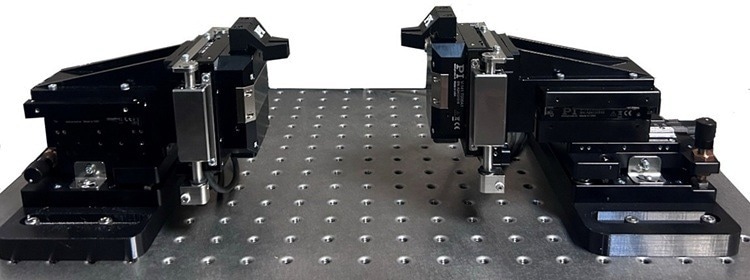
Dual-sided PINovAlign alignment system setup. Special first-light detection algorithms can reduce dual-sided alignment time by several orders of magnitude. Image Credit: PI (Physik Instrumente) LP