Advanced motion control algorithms for precision linear tables and rotary tables achieve ultrafast fast step and settle operations, as well as rapid tracking.
In high performance competition cars, rapid acceleration and precise braking, along with advanced control algorithms to keep the vehicle on an optimized path are key to chasing down fractions of a second. In high precision industrial automation, similar rules apply. Controlling motion with nanometer precision, on a millisecond time scale, once a curiosity in physics laboratories, has become a mainstay in mass manufacturing of fiber-optics and semiconductor related applications and even the latest medical device manufacturing trends are moving in the same direction. Recent advancements in precision motion control, particularly when there is a need for short, high acceleration moves or external signal tracking motion are discussed in the following article.
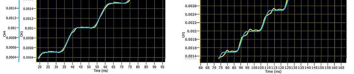
Image Credit: PI (Physik Instrumente) LP
The PI Lead Optimized Translation (PILOT) technology has been specifically developed to improve the performance of direct drive linear tables and rotary motion tables employed in applications utilizing short high acceleration moves and rapid settling, as well as enhancing performance in tracking applications where moves follow an external signal; for example, high speed autofocus systems.
Preventing the Problem
This article outlines results from short dynamic moves of a 2.7 kg mass with tight error bands. These moves took place via a series of repeated 500 nm and 50 µm continuous steps.
The study employed PILOT to ensure optimal error characteristics, enabling excellent dynamics in a compact stage form factor while simultaneously reducing motor heating and enhancing motor performance.
A key advantage of PILOT is that it affords processes the same level of dynamics with less motor current, less error and less injected heat – essentially preventing problems rather than compensating for these after they occur.
PILOT technology can be applied to both direct-drive linear stages and rotary tables.
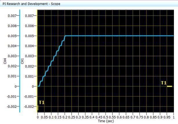
Image Credit: PI (Physik Instrumente) LP
Each move involved 10 successive steps of 500 nm and an artificial 5 msec delay. The blue trace represents the profiled motion, while the yellow trace represents the position of the stage. When these traces are viewed at 1 µm per division, they are almost perfectly overlapped.
The time to complete these 10 moves was 200 msec each, with a complete timescale of a single second.
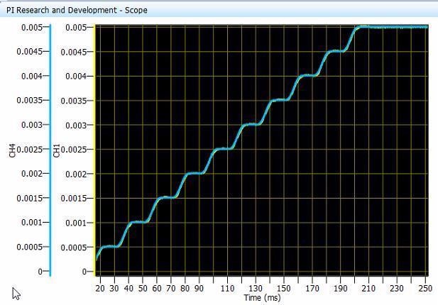
Image Credit: PI (Physik Instrumente) LP
Zooming in to investigate error characteristics (500 nm/div) confirms that the stage motion is following the profiled motion with no notable errors.
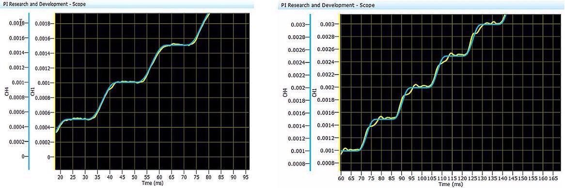
With PILOT Enhanced Motion (left). Without PILOT Enhanced Motion (right). Image Credit: PI (Physik Instrumente) LP
On close inspection (200 nm/div), the benefits of the PILOT controlled motion (left) can be observed in both the step and settle timing and the error characteristics. This is especially notable when compared with results from the same system operated without the use of PILOT algorithms (right).
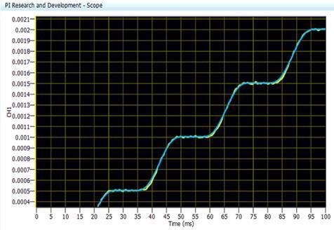
Image Credit: PI (Physik Instrumente) LP
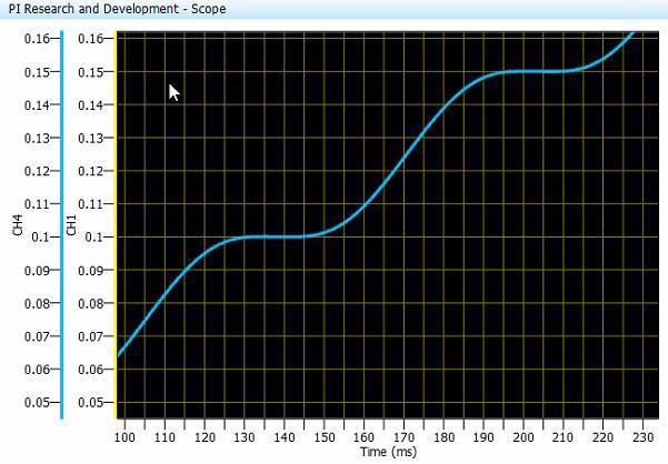
For further comparison, the stage was loaded with an extra 6 kg of mass. The graph illustrates 500 nm steps (100 nm/div) with the additional load resulting in only marginally reduced rise time performance.
The yellow trace (stage position) continues to follow the profiled motion (blue) tightly, confirming that the algorithm offers excellent tracking performance, even under additional load.
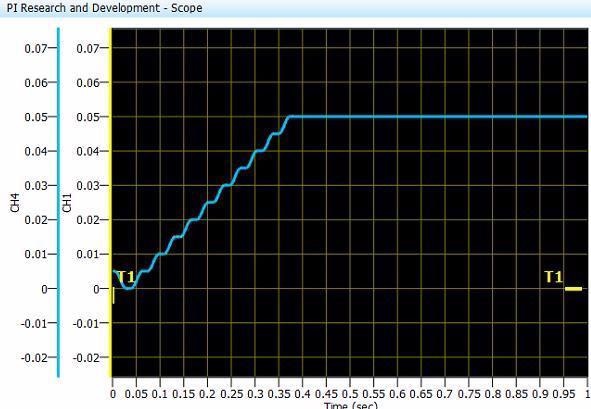
Image Credit: PI (Physik Instrumente) LP
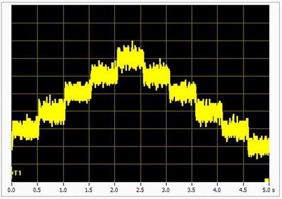
An examination of 50 µm moves made in quick succession under PILOT control (100 µm/div) reveals that a total of 10 moves are made within ~350 msec, also including artificial wait times of 5 msec between each adjacent move.
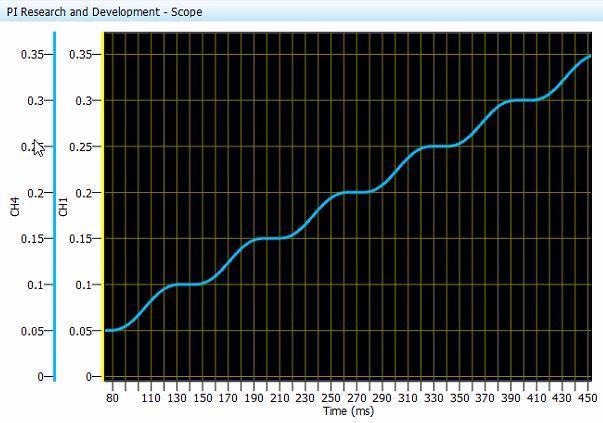
Image Credit: PI (Physik Instrumente) LP
Closer (50 µm/div) inspection of the 50 µm moves reveals that stage motion (yellow trace) is perfectly overlaid with profiled motion (blue trace). Tracking motion is so tightly followed that profiled motion is not visible.
Same 50µm moves as above but 5X higher zoom (10µm/div) - the error is still negligible with PILOT control. Image Credit: PI (Physik Instrumente) LP
Reduction of Heat Dissipation (Motor Current) using PILOT
A key benefit of PILOT controlled motion is the optimization of motor current. Motor current generates heat, negatively impacting performance and potentially inhibiting the use of compact rotary or linear positioning stages. This is because motors are not large enough to accommodate the applied payload under required dynamics.
The graph below illustrates PILOT’s impact on the commanded motor current when employed under the same frequency of motion and/or move timing.
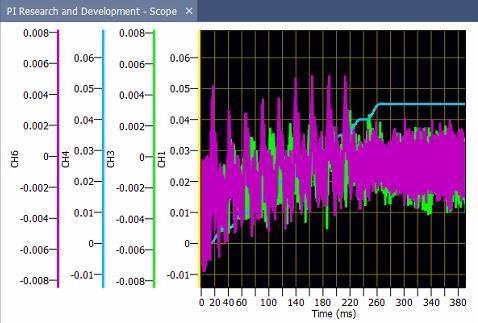
Image Credit: PI (Physik Instrumente) LP
Motor current traces are plotted in relation to commanded moves. with PILOT control shown in green and standard control shown in purple.
The graph illustrates 10 rapid moves that are perfectly overlaid and demonstrate identical move times. PILOT control resulted in an improvement in error characteristics and a 25% reduction in required motor current.
The tests outlined here were run using a V-551 linear motor stage (shown below in its XYZ configuration) alongside an A-814 industrial, EtherCat-based motion controller. PI offers a wide range of linear stages suitable for a number of applications, including super-resolution microscopy and industrial precision automation.
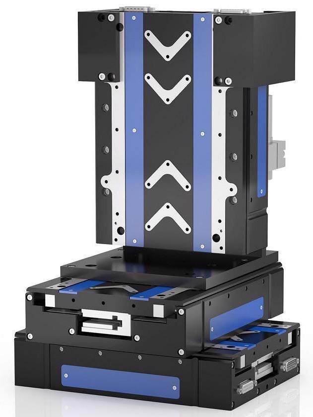
XYZ linear table configuration of V-551 linear motor stage. Image Credit: PI (Physik Instrumente) LP
Nanometer steps performed by high precision linear table. Image Credit: PI (Physik Instrumente) LP
XY-Stage - Direct Drive Linear Stage w/Linear Motor, fast Scanning & Alignment, V-508 Linear Stage
Video 1. High speed active alignment stage of fiber optic components with direct-drive XY-Linear Table, with linear motors and ACS motion controller. Video Credit: PI (Physik Instrumente) LP
Infinite Field of View Laser Galvo Scanner Demo / Gantry - X-Y-Linear Stages w/ Linear Motors, by PI
Video 2. PI XY linear motor stages and galvo scanners in high-speed, high-precision laser beam steering / writing demonstration. Video Credit: PI (Physik Instrumente) LP

This information has been sourced, reviewed and adapted from materials provided by PI (Physik Instrumente) LP.
For more information on this source, please visit PI (Physik Instrumente) LP.