|
Since their discovery in 1991,1 carbon nanotubes (CNTs) and related nanostructures have attracted much attention because of their remarkable electrical, mechanical, and thermal properties.2-5 Many conformations of carbon, including bamboo-structured, carbon cages and carbon nanohorns have been produced under a variety of reaction conditions.6-10 Several studies have reported the synthesis of bamboo-structured CNTs (BCNTs) using Fe, Co and Ni catalysts. For example, bamboo-like structures of CNTs have been synthesized on Ni-loaded graphite and Fe-loaded carbon electrodes using arc-discharge methods.11,12 Wang and coworkers also observed the alignment of BCNT films synthesized through the pyrolysis of iron(II) phthalocyanine on a quartz substrate at 850ºC.13 The authors postulated that the formation of BCNTs was effected by the diameter of the particles used as catalysts. Small Fe particles, of approximately 20 nm, were responsible for the growth of BCNTs, while large Fe particles did not produce BCNTs. Li et al.14 have reported the synthesis of BCNTs by chemical vapor deposition (CVD) using supported Ni catalysts. Lee and Park 15 also obtained aligned BCNTs from Fe-catalyzed vapor deposition of acetylene at temperatures ranging from 550 to 950°C. They observed that most of the tips of the BCNTs were closed and free from the encapsulation of Fe particles above 550ºC, while BCNTs grown at 550 ºC sometimes encapsulated an Fe particle at their tip.
Catalytic Activity
Cu is believed to be an inactive metal with little or no catalytic activity for methane decomposition.16,17 It is, however, wrong to think that copper has no hydrocarbon reforming capability and its role as an active catalyst in hydrocarbon fuel cells is well known.18 Recently, Farmer et al. 19 have grown large diameter carbon fibres (~200 nm) from methane on Cu particles placed on an alumina substrate. The bamboo-like structure of the carbon fibres was found to strongly depend on temperature and BCNTs were only grown at temperatures between 960 and 1018oC. Didik et al. 20 synthesized multi-walled CNTs filled with Cu, Cu2O and CuCl via the carbonization of PVA and CuCl (or CuCl2) at 250ºC. The morphology of the carbon nanostructures produced was independent of the Cu salt used, i.e. CuCl or CuCl2. They suggested that the growth of the nanotubes occurred via carbon diffusion through the metallic particles but this is unlikely at 250ºC. This route can not be considered a classical catalytic-CVD process and bears little significance in terms of the activity of copper metal to cracking of methane for carbon nanotube synthesis.
In this paper we demonstrate that a novel MgO supported bimetallic copper-molybdenum catalyst generates BCNTs by direct catalytic-CVD of methane. This is highly unexpected as Mo has traditionally been used to produce CNTs only as co-catalysts with Co, Fe or Ni due to the energetically favorable formation of a self-poisoning molybdenum carbide phase which prohibits the formation of CNTs.21-23 Furthermore, the only activity for CNT production on supported copper catalyst has come from recent studies of K promoted samples using the much more reactive acetylene carbon source.24 .
Materials and Methods
Preparation of Carbon Nanotubes
BCNTs were synthesized by the catalytic decomposition of methane over a MgO supported Cu and Mo catalyst. Briefly, an MgO support was prepared by the decomposition of Mg2(OH)2CO3 at 450 ºC for 6 hr.25 The support was impregnated from an aqueous solution of Cu(NO3)2.6H2O and (NH4)Mo6O24.H2O. Metal content is given as weight % to the support. In all cases the Mo content was 5 wt.% relative to the support. Energy Dispersive X-ray (EDX) spectra were acquired using an Oxford Instruments Model 6587 EDS Unit. The microscope was operated at 20 kV with collection time of 100 s. Elemental concentrations were calculated using INCA software.
The solution was sonicated for 30 minutes and dried at 100 ºC overnight. The dried powder was sintered at 500 ºC for 6 hr to produce the catalyst. 0.3 g of the catalyst was placed in a quartz tube in a tube furnace. The active metal components were reduced by heating to 850 ºC in 10% H2/Ar at a flow rate of 300 ml min-1 for 30 min. Methane was then fed into the tube at a flow rate of 100 ml min-1. The growth period for BCNTs formation was set at 850 ºC at 60 min, after which the furnace was cooled to room temperature. To isolate BCNTs the as-prepared material was treated with 6 M HNO3 and was washed by water to remove the catalyst.
Characterization
Scanning electron microscopy (SEM) was conducted on a LEO 1530EP scanning microscope. Transmission electron microscopy (TEM) was performed on a Hitachi H7000 operating at 120 kV and on a Philips Tecnai G2 20 operating at 200 kV. Samples for TEM analysis were dispersed in ethanol and deposited onto Cu or Ni grids. Energy-dispersive X-ray analysis (EDXA) was undertaken using an electron beam focused on the area of interest and recorded in the binding energy region of 0 - 20 keV. Raman spectra were recorded on a Renishaw 1000 Raman system in an ambient atmosphere using a 5 mW He-Ne laser (λ = 514.5 nm) and a CCD detector. UV Raman spectra were measured at room temperature with a Jobin-Yvon T64000 triple-stage spectrograph with spectral resolution of 2 cm-1. The 244 nm line from a Coherent Innova 300 Fred laser was used as another excitation source. Thermal gravimetric analysis (TGA) of the carbon sample was performed at a heating rate of 10 ºC min-1 up to 900 ºC in air flow of 75 ml min-1.
Results and Discussion
Figure 1 shows TEM images of a reduced 5 wt.% Mo/MgO catalyst and a carbon/catalyst composite prepared from the Mo/MgO catalyst. No obvious catalyst particles were observed on the surface of the Mo/MgO catalyst after hydrogen reduction. Methane decomposition over this catalyst in the conditions outlined above showed evidence of the formation of amorphous carbon (Figure 1b). There is no evidence of regularly shaped carbon features and the data are consistent with previous evidence of carbide formation in similar conditions.21
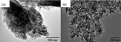
Figure 1. TEM images of (a) 5 wt.% Mo/MgO catalyst reduced at 850 oC for 60 minutes using H2/Ar flow of 200 ml min-1, (b) carbon/catalyst composite prepared on 5 wt.% Mo/MgO at 850oC.
MgO supported Cu catalysts with 5 wt.% Cu did not produce a carbon deposit that could be observed by microscopy. The catalyst powder color is red after the reaction at 850 oC for 1 hr, which is produced by metallic copper. This is clearly related to the established low activity of Cu/MgO for the decomposition of CH4 16 although single particles of Au, Ag and Cu on Al-hydroxide surfaces or Silicon wafers substrate were recently found to be high active for the synthesis of sing-walled carbon nanotubes.26,27
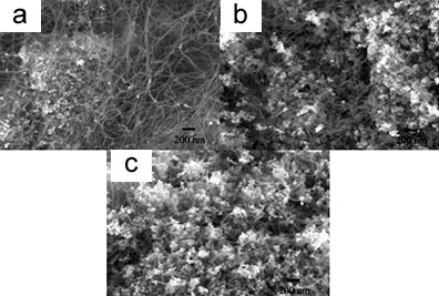
Figure 2. SEM micrographs of bamboo structure carbon nanotubes grown at 850 ºC for 60 minutes on (a) a 5 wt.% Cu-loaded Cu/Mo/MgO, (b) a 10 wt.% Cu-loaded Cu/Mo/MgO and (c) a 15 wt.% Cu-loaded Cu/Mo/MgO catalyst by CVD (Mo loading was 5 wt.% in both cases).
Effect of Copper on Carbon Nanotube Formation
A series of experiments were performed in order to investigate the effect of the Cu additive on the formation of carbon nanotubes. At higher Cu loadings carbon nanotubes with uniform diameters, were formed on 5 wt.%, 10 wt.% and 15 wt.% Cu-loaded Cu/Mo/MgO catalysts, as shown in the SEM data in figure 2. In all cases the surface of the catalyst was covered with CNTs with some of the nanotubes aggregated together. Further detail is provided in the TEM data shown in Figures 3. For a 2 wt.% Cu-loaded Cu/Mo/MgO catalyst amorphous carbon was the main product formed following catalytic CVD, while larger amount of carbon nanotubes are generated on 5 wt.%, 10 wt.% and 15 wt.% Cu-loaded Cu/Mo/MgO catalyst, indicating that Cu plays a key factor on the formation of carbon nanotubes. Careful analysis of these images and similar data show that in all cases that CNTs grew only from nanoparticles with diameters less or equal to 20 nm. The lengths of the CNTs were up to several microns. This can be clearly seen in the figures as no nanotubes growth can be observed on black catalyst nanoparticles (typical of diameters > 40 nm). We suggest that these particles are passivated by carbide formation. This size dependence is the obvious reason for the diameter of the CNTs being around the 20 nm value. A histogram of carbon nanotube diameters shows that the nanotubes have a uniform outer diameter of about 20 nm (Figure 3e).
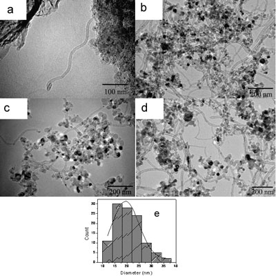
Figure 3. Carbon nanotubes prepared on (a) 2 wt.% Cu-loaded Cu/Mo/MgO, (b) 5 wt.% Cu-loaded Cu/Mo/MgO, (c) 10 wt.% Cu-loaded Cu/Mo/MgO, (d) 15 wt.% Cu loaded Cu/Mo/MgO without treated using 6M HNO3, (e) Histogram of the diameter of carbon nanotubes. The solid lines correspond to a Gaussian fit.
EDXA Measurements
The bimetallic nature of the nanoparticulate catalyst is proven by EDXA measurements which revealed the presence of both Cu and Mo within the particles. For example, typical EDXA data of 10 wt.% Cu-loaded Cu/Mo/MgO catalyst are shown in Figure 4. The signal at 17.4 keV is attributed to Mo, the signal at 8.0 keV and 8.9 keV are assigned to the transition Kα and Kβ1 for Cu. The weight ratio of Cu to Mo is about 2.3, which is slightly higher than that of original catalyst. Note that the signal at 7.4 keV is attributed to Ni Kα transition from the TEM grid.
Figure 4. EDXA spectra of a carbon/catalyst prepared on 10 wt.% Cu-loaded Cu/Mo/MgO catalyst by CH4 CVD at 850oC for 1 hr. Peaks are labelled with reference to accepted x-ray lines.
TEM images following the HNO3 treatment to dissolve the catalyst reveal the nature of the CNTs formed. Figure 5 shows TEM images typical of multi-walled bamboo-structured nanotubes prepared at 850 oC on 10 wt.% Cu-loaded Cu/Mo catalyst. The yield of carbon nanotubes was about 10 wt.% relative to the catalyst weight. The flexible nanotubes formed using these catalysts are shown in Figure 5a. Catalyst particles were often observed at the tips of the nanotubes and in some cases small metal particles were seen inside the nanotubes (Figure 5b). These observations suggest that the ends the BCNTs are closed and this is confirmed by characteristic data shown in Figure 5c.
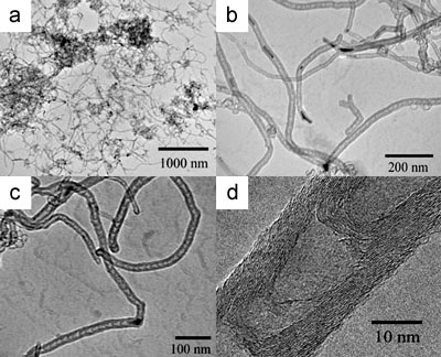
Figure 5. Typical TEM images of BCNTs grown at 850 ºC using a 10 wt.% Cu/Mo/MgO catalyst: (a) low magnification TEM image of BCNTs, (b) TEM image of catalyst particles located inside and at the tips of the nanotubes, (c) TEM image of carbon nanotubes filled with a catalyst nanoparticle which is responsible for the formation of BCNTs with an outer diameter of 20 nm, (d) a high-resolution TEM image of a BCNT with the curved graphite sheets.
Morphologies of Encapsulated Catalyst Particles
Interestingly the catalyst particles encapsulated within the BCNTs did not possess the same sphere-like morphologies observed in unreacted catalysts or unused catalyst particles. This is consistent with the high temperatures used which are in excess of the Hüttig temperature of copper. High resolution TEM images shown in Figure 5d reveal that the walls of the nanotubes are constructed from 10-20 graphitic layers and an inner diameter ranging from 5 to 10 nm.
Figure 6. Raman spectra of BCNTs grown by the catalytic decomposition of CH4 over a Cu/Mo/MgO catalyst at 850 ºC with a Cu loading of: (a) 5 wt.%, (b) 10 wt.% and (c) 15 wt.%.
Bamboo Structured Carbon Nanotube Quality
The quality of the BCNTs is indicated by the Raman spectra shown in figure 6. Two characteristic peaks were observed deriving from the BCNTs. One peak, the D-band, is located at approximately 1326 cm−1 and is attributed to defects, curved graphite sheets and lattice distortions in the carbon structures. The G-band, at about 1588 cm−1, is characteristic of graphite. The intensity of the D-band is stronger than that of the G-band for all three carbon samples, but the intensity of the 1326cm-1 peak decreases with an increase in the amount of Cu in the catalyst. The intensity ratios between the D-band and G-band (ID/IG ratio) were found to be 1.27, 1.20 and 1.09 for Cu loadings of 5, 10 and 15 wt.% respectively, indicating that higher quality nanotubes are formed at the higher Cu/Mo ratio in our experiments.
The better quality of BCNTs formed at higher copper loadings is also indicated by thermal gravimetric analysis (TGA) as shown in figure 7 for materials produced at 5 wt.% and 15 wt.% Cu-loaded Cu/Mo/MgO catalysts. These data indicate that combustion of the BCNTs occurs at 452 ºC and 476 oC for the lower and higher Cu loading respectively. The higher gasification temperature is consistent with a higher degree of crystallinity for the high Cu loading. The gasification temperatures observed here are some 200 – 300 °C lower than for high quality multi-walled CNTs (MCNTs) in our experiment. The lower BCNTs combustion temperature is probably related to greater defect densities in the BCNTs compared to MCNTs. Residual metal might also act as a combustion catalyst for the oxidation of carbon but this is considered unlikely because of the closed nature of the BCNTs described above.
Figure 7. TGA of BCNTs grown by the catalytic decomposition of CH4 over a Cu/Mo/MgO catalyst at 850 ºC with a Cu loading of (a) 5 wt.%, (b) 15 wt.% and MCNTs prepared by methane decomposition on Co/Mo/MgO. Inset is the TEM image of MCNTs prepared by methane decomposition on Co/Mo/MgO at 800 oC. The loadings of Co and Mo are 4 wt.% and 6 wt.% relative to the MgO, respectively.
The mechanism of BCNTs generation on these systems is complex and unproven at this stage and may be different from that on Mo-promoted Ni, Fe and Co catalyst system.28-30 In order to understand Cu effect on the formation of BCNTs, further experiments of catalyst characterizations were performed using UV-Raman and XRD which shown in figure 8 and figure 9. Figure 8 shows UV resonance Raman spectra of molybdate species supported on MgO excited by the laser line at 244 nm. After the calcination at 450 oC, no Raman signal was found on supported Cu catalyst only, while on 5 wt.% Mo/MgO catalyst, three obvious Raman bands at 736, 820 and 912 cm-1 are observed for the molybdate species. The band at 736cm-1 is attributed to Mo-O-Mg bond, the band at 820 cm-1 is assigned to Mo species of crystalline phase, and the band at 912 cm-1 is attributed to the tetrahedral molybdate species on MgO.
However, two Raman bands at 736 and 820 cm-1 of three Cu-loaded Mo/MgO catalysts disappeared and only one broadened band at 912 cm-1 is left, which should be the contribution of the tetrahedral molybdate species of MgMo4 and CuMo4 phase. However, no carbon nanotubes were found when single Mo is supported on MgO although MgMo4 is measured in the experiments, thus effect of MgMo4 phase on the generation of BCNTs is excluded. This result means that molybdate phase of CuMo4 is only one precursor of reduced nanoparticles, which is responsible for the formation of carbon nanotubes.
Figure. 8. UV resonance Raman spectra of calcined catalysts excited by the laser line at 244.0 nm. (a) 5 wt.% Cu/MgO, (b) 5 wt.% Mo/MgO, (c) 5 wt.% Cu-loaded Cu/Mo/MgO, (b) 10 wt.% Cu-loaded Cu/Mo/MgO and (c) 15 wt.% Cu-loaded Cu/Mo/MgO catalyst.
XRD Patterns of Catalysts
XRD patterns of reduced 5 wt.% Mo/MgO catalyst in figure 9 exhibit that no peaks of metallic Mo are observed and only the characteristic peaks of magnesium oxide appeared. However, weak metallic Mo peaks located near 40 and 58 o can be observed on 10 wt.% Cu-loaded Cu/Mo/MgO. Therefore, Raman and XRD results indicate that the tetrahedral molybdate species play a key role in the formation of Mo nanoparticles for the generation of BCNTs.
Figure 9. XRD patterns of (a) 5 wt.% Mo/MgO catalyst and (b) 10 wt.% Cu-loaded Cu/Mo/MgO catalyst reduced at 850 oC for 60 minutes using H2/Ar flow of 200 ml min-1.
For Mo catalysts single Mo nanoparticles for the synthesis of BCNTs could not be formed without adding Cu in the catalyst, and supersaturation of carbon occurs to form molybdenum carbide which results only in the formation of amorphous carbon, as observed by TEM.31,32 As revealed here, Cu/MgO also does not possess any activity for the decomposition of methane in this temperature range due to the poor hydrocarbon cracking activity of this metal. For the bimetallic catalysts we suggest that Mo centres serve as hydrocarbon cracking centres producing carbide and atomistic carbon species which diffuse to copper containing components and are dispelled forming the BCNTs. The nanoparticle size dependence observed here (i.e. only at particles <20 nm in size) might be related to several effects including particle size effects (inherent higher activity), differing surface composition (due to size related segregation phenomena e.g.) or due to mass transport phenomena at the bimetallic catalyst surface.
Conclusions
In summary, we have successfully synthesized BCNTs using the catalytic decomposition of methane over supported Cu/Mo catalysts. The resultant diameter of the BCNTs is around 20 nm with lengths up to several microns. Only catalyst nanoparticles, with diameters around 20 nm, are active for development of BCNTs. For successful growth of BCNTs both Cu and Mo must be present. Raman spectroscopy and TGA characterisation of the BCNTs indicate that as the Cu content in the catalyst increases so does the yields of high quality nanotubes.
Acknowledgements
The authors acknowledge the European Union under the DESYGN-IT project (STREP Project 505626-1), Enterprise Ireland (Project IP/2004/0183) and Intel (Ireland). We thank Prof. Can Li and Dr. Zhaochi Feng for help in UV-Raman measurements.
|
|
1. Iijima S., “Helical Microtubules of Graphitic Carbon”, Nature, 354(6348), 56-58, 1991.
2. Chauvet O., Benoit J. M., Corraze B., “Electrical, Magneto-Transport and Localization Of Charge Carriers in Nanocomposites Based On Carbon Nanotubes”, Carbon, 42(5-6), 949-952, 2004.
3. Liu J. Z., Zheng Q. S., Wang L. F., Jiang Q., “Mechanical Properties of Single-Walled Carbon Nanotube Bundles as Bulk Materials”, J. Mech. Phys. Solids, 53(1), 123-142, 2005.
4. Sun C. Q., Bai H. L., Tay B. K., S.Li, Jiang E. Y., “Dimension, Strength, and Chemical and Thermal Stability of a Single C-C Bond in Carbon Nanotubes”, J. Phys. Chem. B, 107(31), 7544-7546, 2003.
5. Mingo N., Broido D. A., “Length Dependence of Carbon Nanotube Thermal Conductivity and the Problem of Long Waves", Nano Lett., 5(7), 1221-1125, 2005.
6. Zhang X. X., Li Z. Q., Wen G. H., Fung K. K., Chen J., Li Y., “Microstructure and Growth of Bamboo-Shaped Carbon Nanotubes”, Chem. Phys. Lett., 333(6), 509-513, 2001.
7. Lee C. J., Park J., Kim J. M., Huh Y., Lee J. Y., No K. S., “Low-Temperature Growth of Carbon Nanotubes by Thermal Chemical Vapor Deposition Using Pd, Cr, And Pt As Co-Catalyst”, Chem. Phys. Lett., 327(5-6), 277-283, 2000.
8. Oku T., Suganuma K., “Carbon Nanocage Structures Formed by One-Dimensional Self-Organization of Gold Nanoparticles”, Chem. Comm., 23, 2355-2356, 1999.
9. Saito Y., Matsumoto T., “Carbon Nano-Cages Created by Nanotubes”, Nature, 392(6673), 237-237, 1998.
10. Liu J., Xu L., Zhang W., Lin W., Chen X., Wang Z., “Formation of Carbon Nanotubes and Cubic and Spherical Nanocages” J. Phys. Chem. B, 108(52), 20090-20094, 2004.
11. Saito Y., Yoshikawa T., “Bamboo-Shaped Carbon Tube Filled Partially with Nickel”, J. Cryst. Growth, 134(1-2), 154-156, 1993.
12. Li Y. F., Qiu J. S., Zhao Z. B., Wang T. H., Wang Y. P., Li W., "Bamboo-Shaped Carbon Tubes from Coal”, Chem. Phys. Lett., 366(5-6), 544-550, 2002.
13. Li D., Dai L., Huang S., Mau A., Wang Z., “Structure And Growth of Aligned Carbon Nanotube Films by Pyrolysis”, Chem. Phys. Lett., 316(5-6), 349-355, 2000.
14. Li Y., Chen J., Ma Y., Zhao J., Qin Y., Chang L., “Formation Of Bamboo-Like Nanocarbon and Evidence for the Quasi-Liquid State of Nanosized Metal Particles at Moderate Temperatures” Chem. Comm., 10, 1141, 1999.
15. Lee C., Park J., “Growth Model for Bamboolike Structured Carbon Nanotubes Synthesized Using Thermal Chemical Vapor Deposition”, J. Phys. Chem. B, 105(12), 2365-2368, 2001.
16. Horita T., Yamaji K., Kato T., Sakai N., Yokokawa H., “Imaging Of Labeled Gas Movements at The SOFC Electrode/Electrolyte Interfaces”, Solid State Ionics, 169, 105-113, 2004.
17. Liao M., Au C., Ng C., “Methane Dissociation on Ni, Pd, Pt and Cu Metal (111) Surfaces — A Theoretical Comparative Study”, Chem. Phys. Lett., 272(5-6), 445-452, 1997.
18. Gorte R.J., Park S., Vohs J.M. and Wang C., “Anodes for Direct Oxidation of Dry Hydrocarbons in a Solid-Oxide Fuel Cell”, Adv. Mater. 12(19), 1465-1469, 2000.
19. Farmer B., Holmes D., Vandeperre L., Stearn R., Clegg W., MRS fall meeting on nanomaterials for structural applications, Warrendale, PA, Boston, 2002, p 81.
20. Didik A., Kodolov V., Volkov A., Volkova E., Hallmeier K., "Low Temperature Growth of Carbon Nanotubes”, Inorg. Mater., 39(6), 583-587, 2003.
21. Shajahan M., Mo Y., Fazle Kibria A., Kim M., Nahm K., “High Growth of SWNTs and MWNTs from C2H2 Decomposition over Co–Mo/MgO Catalysts”, Carbon, 42(11), 2245-2253, 2004.
22. Herrera J., Resasco D., “Loss of Single-Walled Carbon Nanotubes Selectivity by Disruption of the Co–Mo Interaction in The Catalyst”, J. of Catal., 221(2), 354-364, 2004.
23. Choi Y., Cho W., “Synthesis of Y-junction Single-wall Carbon Nanotubes”, Carbon, 43(13), 2737-2741, 2005.
24. Tao X., Zhang X., Cheng J., Wang Y., Liu F., Luo Z., “Synthesis of Novel Multi-Branched Carbon Nanotubes with Alkali-Element Modified Cu/Mgo Catalyst”, Chem. Phys. Lett., 409(1-3), 89-92, 2005.
25. Li Q., Yan H., Cheng Y., Zhang J., Liu Z., “A Scalable CVD Synthesis of High-Purity Single-Walled Carbon Nanotubes with Porous Mgo as Support Material”, J. Mater. Chem., 12, 1179-1183, 2002.
26. Takagi D., Homma Y., Hibino H., Suzuki S., Kobayashi Y., “Single-Walled Carbon Nanotube Growth from Highly Activated Metal Nanoparticles”, Nano Lett. 6(12), 2642-2645, 2006.
27. Zhou W., Han Z., Wang J., Zhang Y., Jin Z., Sun X., Zhang Y., Yan C., Li Y., “Copper Catalyzing Growth of Single-Walled Carbon Nanotubes on Substrates”, Nano Lett. 6(12), 2987-2990, 2006.
28. Zhou L., Ohta K., Kuroda K., Lei N., Matsuishi K., Gao L., Matsumoto T., Nakamura J., “Catalytic Functions of Mo/Ni/MgO in the Synthesis of Thin Carbon Nanotubes”, J. Phys. Chem. B, 109(10), 4439-4447, 2005.
29. Alvarez W., Pompeo F., Herrera J., Balzano L., Resasco D., “Characterization of Single-Walled Carbon Nanotubes (SWNTs) Produced by CO Disproportionation on Co-Mo Catalysts”, Chem. Mater. 14(4), 1853-1858, 2002.
30. Hu M., Murakami Y., Ogura M., Maruyama S., Okubo T., “Morphology and Chemical State of Co–Mo Catalysts for Growth of Single-Walled Carbon Nanotubes Vertically Aligned on Quartz Substrates”, J. of Catal., 225(1), 230-239, 2004.
31. Tang S., Zhong Z., Xiong Z., Sun L., Liu L., Shen Z. and Tan K. L., “Controlled Growth of Single-Walled Carbon Nanotubes by Catalytic Decomposition of CH4 Over Mo/Co/Mgo Catalysts”, Chem. Phys. Lett., 350(1-2), 19-26, 2001.
32. Wu W., Wu Z., Liang C., Ying P., Feng Z., Li C., “An IR Study on The Surface Passivation of Mo2C/Al2O3 Catalyst with O2, H2O And CO2”, Phys. Chem. Chem. Phys., 6, 5603-5608, 2004.
|