A well-established technique in industry, laser micromachining uses lasers to mark, cut, and drill workpieces with extremely high precision.1 Using ultrashort pulsed lasers, laser-based solutions are increasingly being adopted within sample preparation for microscopy.
The recently commercialized standalone lasers and integrations with FIB-SEM instruments, so-called LaserFIBs, are for this purpose.2,3,4 Ultrashort laser pulses in the femtosecond (fs) range result in minimal sample damage and heat-affected zones (HAZ).
Additionally, fs lasers enable the rapid yet precise removal of material. For example, the fs laser utilized on a ZEISS Crossbeam laser can remove up to 15 µm³ of silicon per second using a probe size of <15 µm diameter. Figure 1 presents the ZEISS Crossbeam laser.
The laser work is carried out in a separate dedicated chamber (in the foreground) to prevent contamination of the FIB-SEM main chamber. During this work, the sample is shuttled between the laser and the main chambers, while site-specific work is conducted by simply handshaking SEM and laser coordinates.
This article presents the coordinate registration process and how this process may be improved to ensure laser targeting of the ROI with less than 2 µm precision for local areas. This level of accuracy facilitates closer milling to the ROI by laser, reducing FIB processing time and overall time-to-result.
Laser Registration
Figure 2 presents a schematic of the Crossbeam laser workflow for a site-specific preparation. The sample is positioned on a special sample holder (see inset) with four distinct fiducials utilized for registration purposes, as described below.
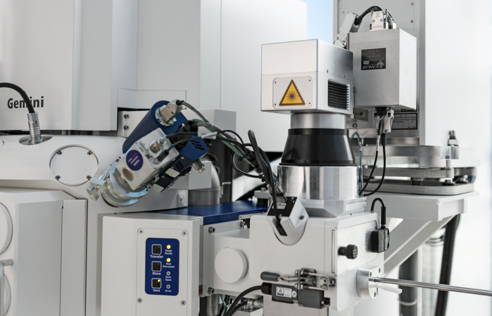
Figure 1. ZEISS Crossbeam laser. Image Credit: Carl Zeiss Microscopy GmbH
The first step is locating the ROI (or multiple ROIs) in the SEM (Figure 2A). This is a critical step because the ROI is typically buried deep below the surface.
It is assumed that the coordinates of the ROI are known, based on the structure of the sample (such as an interface in a layered system), a CAD layout, or a previous characterization by a non-destructive 3D imaging technique (such as CT or X-Ray microscopy (XRM)).
The 3D CAD or XRM data is imported into the FIB-SEM user interface and is subsequently correlated with the SEM image of the surface. The target coordinates relate to a specific location on the SEM image, SEM stage position, and depth.
The SEM image is obtained as a reference at the location of the ROI employing an appropriate magnification, as later required for the precise positioning of the laser milling pattern.
Following this, the sample holder and SEM coordinate systems are aligned using the automatic centering of the four sample holder fiducials under SEM observation (as shown in Figure 2B). This allows the position of the ROI relative to the fiducials to be determined.
The sample is transferred to the laser preparation chamber attached to the airlock (as seen in Figure 2C) for laser work. In a secondary registration step (see Figure 2D), the laser scans small areas surrounding the four fiducials to measure their precise position in the coordinate system of the laser scanning unit.
This locks the laser and SEM coordinate systems, allowing laser patterning objects to be positioned on the previously recorded SEM image of the ROI and exposed (as shown in Figure 2E).
To continue FIB-SEM work following laser milling, the sample is placed back in the main chamber of the instrument to complete the workflow (as shown in Figure 2F).
This workflow enables a feature to be targeted within an area of 25 mm × 25 mm5 with an accuracy of less than 15 µm. This value is identical to the diameter of the laser beam and can be further enhanced by conducting local offset corrections.
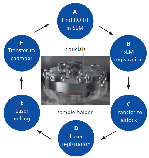
Figure 2. The Crossbeam laser workflow for site-specific preparation is shown schematically. Image Credit: Carl Zeiss Microscopy GmbH
Improving Laser Accuracy with Local Offset Corrections
Consider the primary sources of error that impact the targeting accuracy of the laser. These are related to errors in:
- Laser registration
- SEM registration
- Laser scan field calibration.
For a given SEM registration, the second error is constant while the position of the sample about the fiducials of the sample holder (see inset of Figure 2) remains unchanged.
The third error relies on the uniformity of the laser projection optics and the laser focus or the height of the sample.
Utilizing a local offset correction specific to the sample and area of work allows the experimental determination and correction of errors 2 and 3. This means that the only remaining source of error is the laser registration.
The residual error within an area of approximately 1 mm × 1 mm around the ROI is less than 2 µm, as demonstrated in the following section.
Figure 3 presents the local offset correction method. For this case, a silicon wafer is utilized as the sample. A fabricated ROI was protected using an ion-beam-induced deposition (IBID) of carbon (see Figure 3a).
The IBID is square and has a nominal side length of 2 µm. Two fiducials were machined using FIB, next to the ROI. Alternatively, any distinct features on the sample could have been utilized. The entire process presented in Figure 2 was performed once, aiming for the left fiducial.
As displayed in Figure 3b, the target was missed by |∆x| = 2.17 µm in the x-direction and |∆y| = 0.53 µm in the y-direction. This was measured as the distance between the laser spot's circular outline and the target's centers. The laser scan field calibration was corrected by adding ∆x and ∆y as an offset.
A second iteration was conducted to further improve the offset correction, where the right fiducial was targeted, removing step B of the workflow (as shown in Figure 2) and preserving the SEM registration. The result is shown in Figure 3c, demonstrating that the targeting accuracy was further improved.
A new offset of (|∆x|, |∆y|) = (0.34 µm, 1.62 µm) was measured and corrected. Further iterations are unnecessary as they would not further improve the targeting accuracy.
Following the two local offset corrections, laser machining around the ROI may be carried out with a precision better than ±2 µm.
Approximately 10 minutes are added to the total time by the local offset corrections for the single, and less than 15 minutes are added for the double local offset correction.
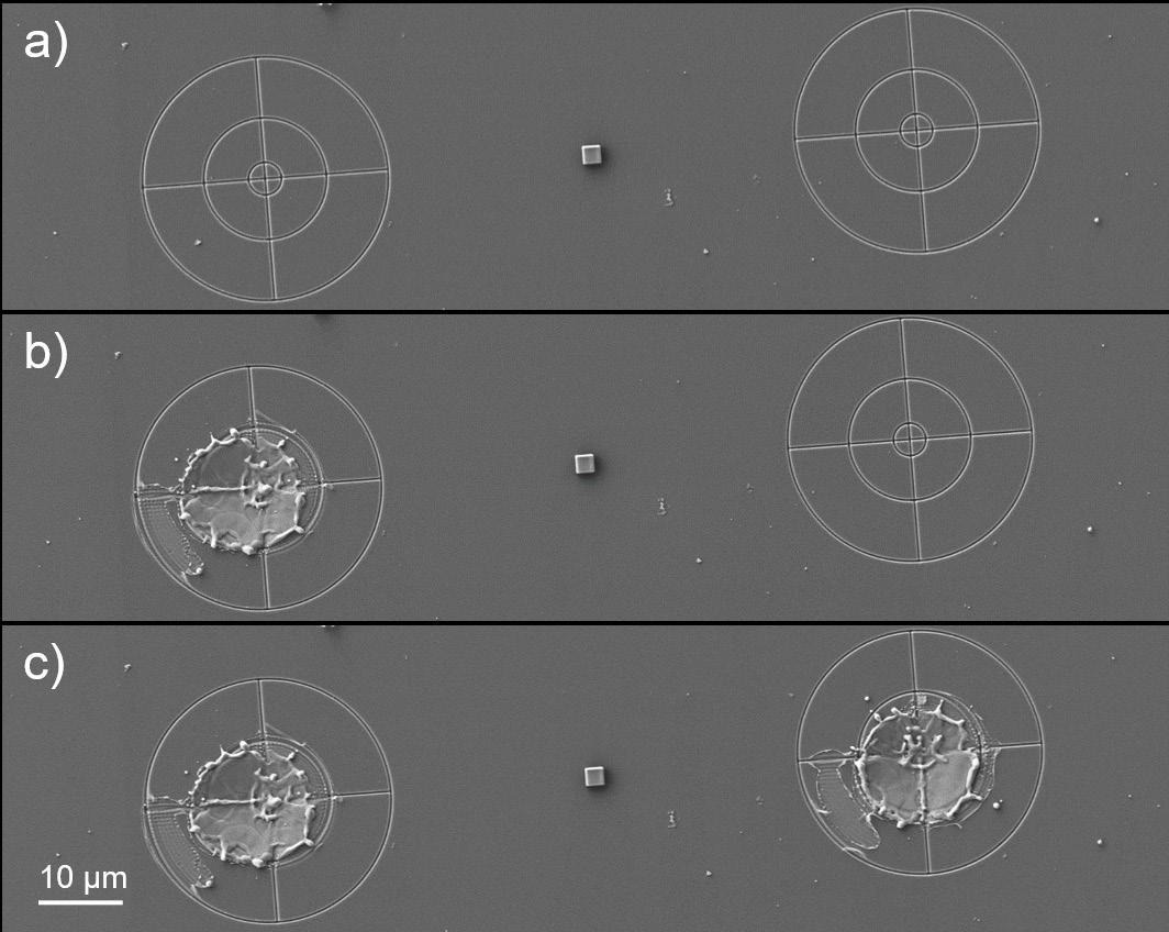
Figure 3. Illustration of the local offset correction method: a) Two FIB-machined targets were patterned near the ROI. The SEM image a) was used as a reference to guide the laser. b) The offset between SEM and laser is measured and corrected for (first offset correction). c) The second fiducial was targeted to further refine the local offset correction (second offset correction). Image Credit: Carl Zeiss Microscopy GmbH
Quantifying the Laser Targeting Accuracy
The following experiment was performed to quantify and obtain further statistics regarding achievable laser targeting accuracy. An array of 3 x 3 fiducials was machined on a silicon chip using FIB to supply nine test sites. The fiducials are comprised of a cross and two concentric circles, as illustrated in the inset of Figure 4.
The inner circle has a radius of 2 µm, corresponding to the targeting accuracy specification utilizing a double local offset correction. The outer circle has a diameter of 15 µm, the nominal spot size of the fs laser beam.
An SEM image of each fiducial was obtained and stored as an ROI for the laser experiment. An initial frame measuring 80 µm × 80 µm was machined by laser around a fiducial outside the array, following the workflow presented in Figure 2.
The targeting accuracy was determined, as shown in Figure 4, by measuring the distance, 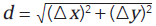 , between the center of the FIB fiducial and the crossing point of the frame diagonals.
The local offset correction (∆x, ∆y) was applied to the laser scan field calibration. A second local offset correction was performed utilizing the top left fiducial of the array (fiducial 1 in Table 1) and kept constant for the duration of the experiment.
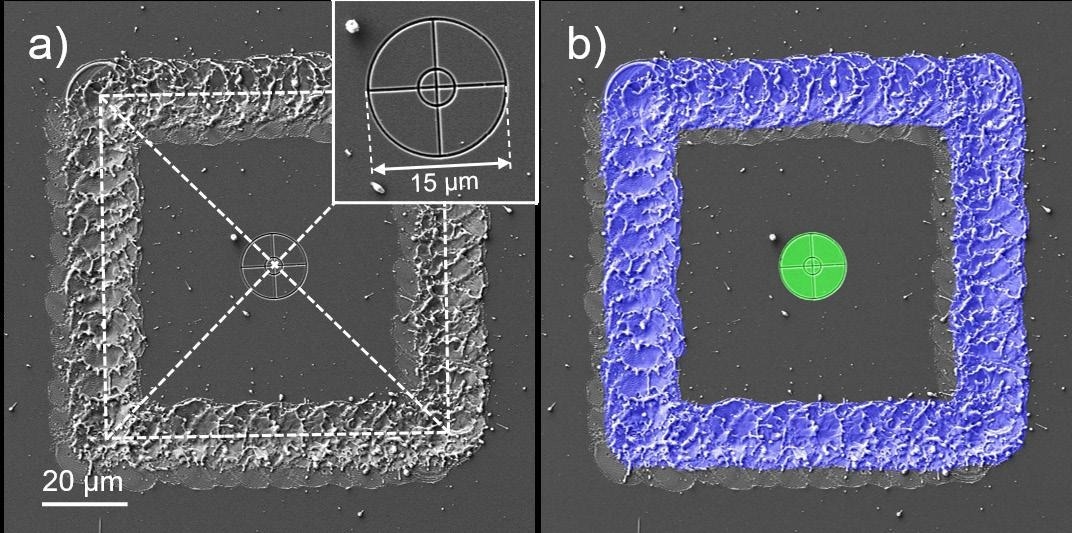
Figure 4. Laser-targeting accuracy measurement for one of the fiducials. a) Manual measurement. b) Measurement using automatic segmentation. Image Credit: Carl Zeiss Microscopy GmbH
Following this, laser frames were exposed to target all remaining FIB fiducials, with a new laser registration being carried out before each next exposure.
The following procedure was iterated for fiducials 2 to 9:
- The shuttle sample holder is transported to the laser preparation chamber.
- The automatic laser registration is triggered.
- The laser frame is centered around the targeted fiducial on the corresponding SEM reference image.
- The laser pattern is exposed.
- The sample holder is returned to the main chamber to report the result.
- Repeat for the next fiducial.
Figure 5 presents images documenting the laser milling result after the second, fourth, sixth, and eighth iterations.
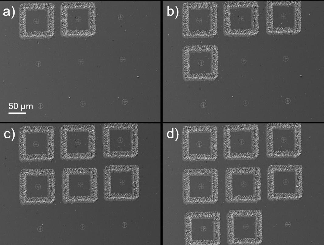
Figure 5. SEM images of a 3 × 3 array of FIB fiducials after laser exposure of a frame around the fiducial number a) 2, b) 4, c) 6, and d) 8. Image Credit: Carl Zeiss Microscopy GmbH
To enable an automated user-independent quantification, machine learning-based segmentation using Intellesis, a module of the AI Toolkit of the software Zen core was employed to calculate the deviation (∆x, ∆y) for each fiducial.6
Three similar images (which was not part of this experiment to avoid training bias) were utilized to train a deep neural network for segmenting the laser tracks and FIB fiducials. The training was conducted using arivis Cloud, the open online image analysis and machine learning platform.7
The network was imported into Intellesis to deliver the automated analysis of the SEM images. The output of this segmentation was two objects for the laser track and the FIB fiducial for each image. The coordinates of the centers of mass for both objects were determined, and the distance, d, was calculated using their difference (∆x, ∆y).
Table 1. Results of the Intellesis analysis for the nine fiducials shown in Figure 5. Source: Carl Zeiss Microscopy GmbH
| Fiducial |
Δx |
Δy |
d |
| 1 |
3.04 |
-3.77 |
4.84 |
| 2 |
0.72 |
-0.96 |
1.20 |
| 3 |
1.95 |
-1.00 |
2.19 |
| 4 |
-0.68 |
-1.82 |
1.94 |
| 5 |
0.11 |
0.43 |
0.44 |
| 6 |
-0.93 |
-0.83 |
1.25 |
| 7 |
-0.98 |
-0.25 |
1.02 |
| 8 |
-1.45 |
1.20 |
1.88 |
| 9 |
0.68 |
-0.62 |
0.92 |
| Average (2–9) |
|
|
1.4 ± 0.6 |
Table 1 presents a summary of the results. Fiducial 1 was utilized for the local offset correction. The average targeting accuracy was d = (1.4 ± 0.6) µm for fiducials 2 to 9. A second experiment was designed to confirm that a distance less than or equal to 2 µm is attainable at any location within the laser writing field.
Four Crossbeam laser systems were surveyed. For each system, nine locations over the central scan field area of 25 × 25 mm were considered, as shown in Figure 6. Each site contained an array of fiducials targeted using a laser, as in the previous experiment.
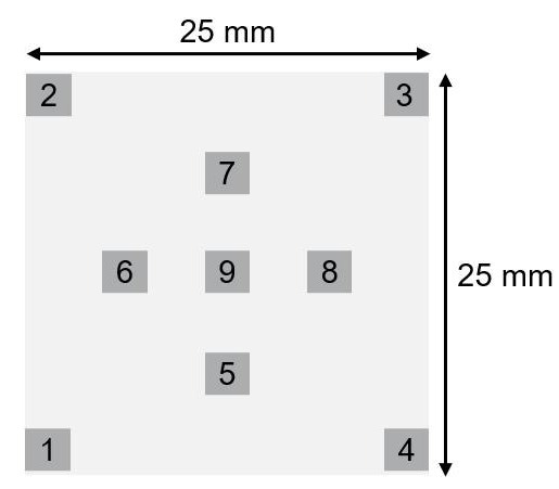
Figure 6. Schematic showing the nine sites for which the laser targeting accuracy was measured after a single and a double offset correction. The sites span an area of 25 × 25 mm. Image Credit: Carl Zeiss Microscopy GmbH
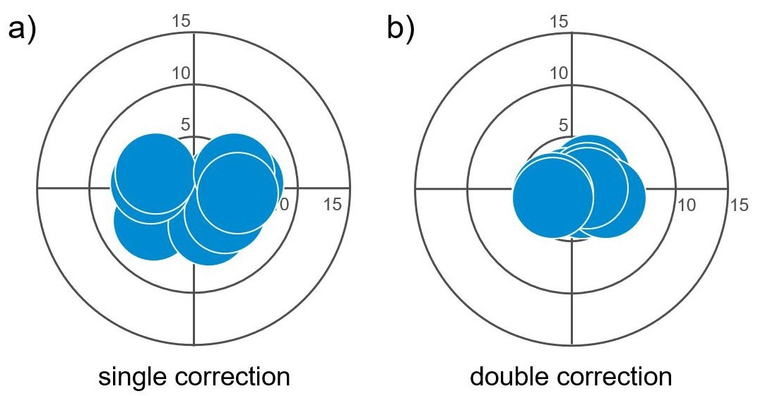
Figure 7. Visualization of the laser targeting accuracy for targets distributed across an area of 25 × 25 mm as shown in Figure 6. For clarity, the laser spots are half their nominal size of 15 µm. Image Credit: Carl Zeiss Microscopy GmbH
Figure 7 provides an example, displaying the measured values (∆x, ∆y) obtained on one of the four instruments after performing the first and second local offset corrections. In the plots, the laser spot is scaled to 50% of its nominal size of 15 µm.
Following the first offset correction, the measured average targeting accuracy is d1 = (4.3 ± 0.8) µm, which improves to d2 = (1.8 ± 0.7) µm after two local offset corrections. However, a third local offset correction did not improve the result.
It is worth noting that d1 and d2 are considerably smaller than the diameter of the laser spot.
Site-Specific Sample Preparation Using the Double Local Offset Correction Method – An Example
Figure 8 illustrates the sample preparation for the local electrode atom probe (LEAP) in silicon employing the double local offset correction method. The ROI was marked and protected using a circular IBID of carbon with a 2 µm diameter (FIB parameters: 30 kV, 50 pA).
The target fiducials' ROI protection and FIB machining (30 kV, 1.5 nA) were carried out utilizing a pre-stored recipe with a total exposure time of 4 minutes and 17 seconds.
A double local offset correction was performed, which took approximately 15 minutes to complete. Subsequently, a pillar was laser machined in the sample containing the ROI, as seen in Figure 8b.
The laser-machined area has an inner diameter of 38 µm and an outer diameter of 500 µm. The material surrounding the ROI was removed to a depth of 120 µm in only 29 seconds.
Subsequently, the atom probe specimen was shaped using standard FIB milling employing a pattern of concentric rings of decreasing sizes and FIB currents (ranging from 30 nA to 700 pA) centered around the ROI (as shown in Figure 8c).8
This step resulted in an addition of 22 minutes and 29 seconds to preparation. The final LEAP sample is displayed in Figure 8d, at 20 µm tall and with a tip radius of 60 nm. The IBID can be observed at the top of this tip. The entire preparation required less than 45 minutes.
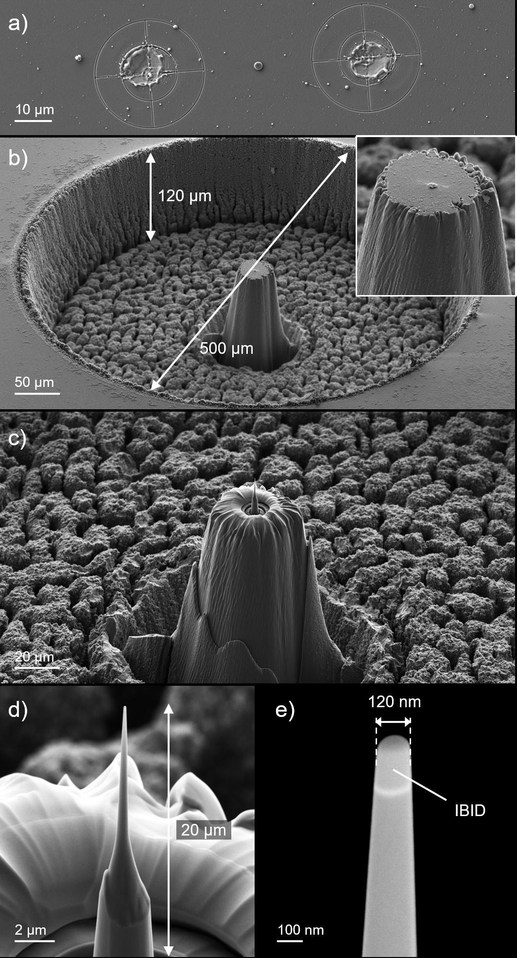
Figure 8. Laser-assisted preparation of a sample for the LEAP. a) The double local offset correction method allows targeting the ROI with better than 2 µm accuracy. b) Sample after the laser machining step. The inset shows the ROI inside the pillar. c) Pillar after the FIB machining step. d) The LEAP sample is 20 µm tall. e) The Inlens SE image shows the IBID. The radius of curvature of the tip is 60 nm. Image Credit: Carl Zeiss Microscopy GmbH
Summary
This article has presented the laser registration process that allows site-specific sample preparation using a ZEISS Crossbeam laser. Various factors restrict the achievable laser targeting accuracy.
The contribution of all but one of these factors may be determined experimentally and corrected using the local offset correction method.
Following the first local offset correction, the targeting accuracy is approximately improved by a factor of three. With a second iteration of local offset correction, the laser targeting accuracy may be further improved to better than 2 µm.
Such high accuracy enables site-specific sample preparation workflows involving massive material removal and the precise FIB machining being highly efficient, as demonstrated by using a sample preparation for the LEAP.
Acknowledgments
Produced from materials originally authored by Tobias Volkenandt, Stephan Hiller, Camille Stebler, and Fabián Pérez-Willard at Carl Zeiss Microscopy GmbH, Oberkochen, Germany.
References and Further Reading
- J. Meijer et al., Laser Machining by short and ultrashort pulses, state of the art and new opportunities in the age of the photons, CIRP Ann.Manuf. Technol. 51 (2002), pp. 531–550.
- https://3d-micromac.com/laser-micromachining/products/microprep/
- M.P. Echlin et al., The TriBeam system: Femtosecond laser ablation in situ SEM, Mater. Charact. 100 (2015), pp 1–12.
- B. Tordoff et al., The LaserFIB: New Application Opportunities Combining a High-Performance FIB-SEM with Femtosecond Laser Processing in a Second Integrated Chamber, Appl. Microsc. 50 (2020), pp. 1–11.
- The total laser scan range is 40 x 40 mm.
- https://www.zeiss.com/microscopy/en/products/software/zeiss-zen-core.html
- https://www.arivis.com/products/cloud-ai
- FIB-SEM Fabrication of Atom Probe Specimens with ZEISS Crossbeam, ZEISS Application Note (2021), https://zeiss.widen.net/s/bjrw8phmjs/en_wp_crossbeam_fib-sem_atom_probe_specimens

This information has been sourced, reviewed and adapted from materials provided by Carl Zeiss Microscopy GmbH.
For more information on this source, please visit Carl Zeiss Microscopy GmbH.