Sponsored by Nanosurf AGJan 22 2024Reviewed by Olivia Frost
Neuromorphic computing refers to computer hardware that diverges from the conventional bi-state logic elements (0 and 1 states) and aims to emulate the behavior of the brain to conduct tasks, utilizing analog signals rather than the standard binary signals.1,2

Image Credit: Shutterstock.com/ArtemisDiana
The most apparent benefit of this method is that, when conducting specific tasks, it is possible to ask the neuromorphic hardware directly rather than having to estimate the behavior of a system numerically utilizing numerous resources (for example, to generate a random number). It incorporates an accurate random process, saving time and energy.
Among the numerous attempts to create neuromorphic devices, one that gained significant attention recently revolves around artificial spin ice structures.
Spin ice refers to a broad spectrum of materials, where, because of the magnetization, there are numerous ground states. The geometrical confinement of the magnetization, such as atoms with net spin arranged in a crystal lattice, induces frustration in the system, resulting in uncompensated magnetic moments.
An especially interesting case, termed artificial spin ice, is by applying magnetic material patterned to nanostructures. Typically, the magnetization within these nanostructures is constant, and it is the spatial distribution of the nanostructures that control the frustration.
Artificial spin ice is important for computation, as demonstrated by its ability to combine computation and memory.2,3
To investigate artificial spin ice, this study utilized Nanosurf’s variable magnetic field sample holder (VMFSH)—an accessory for Nanosurf’s CoreAFM, DriveAFM, and FlexAFM. This accessory facilitates atomic force microscopy (AFM) measurements in a variable in- or out-of-plane magnetic field.
This is particularly valuable when imaging magnetic samples with magnetic force microscopy (MFM).
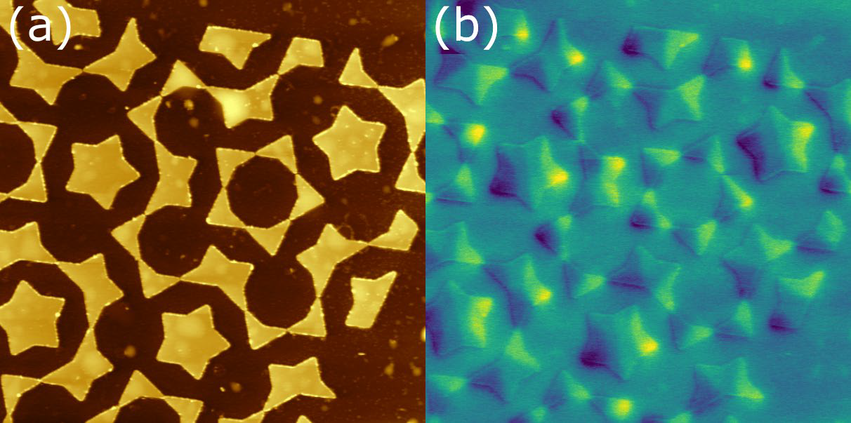
Figure 1. (a): Topography showing magnetic nanostructures alongside some surface contamination (most likely fabrication residue). (b): MFM phase signal taken at zero magnetic field showing the distribution of the stray magnetic field above the sample. Tip lift height first pass amplitude plus 120 nm. Image size: 13×13 μm2. Phase range: 0.3 deg. Image Credit: Nanosurf AG
Materials and Methods
A sample composed of patterned Permalloy (Ni80Fe20) was studied. Permalloy is recognized as a soft magnetic material, and the aspect ratio of the structures employed here confines the magnetization to in-plane domains.
The pattern utilized here is called the Penrose pattern, also named Penrose tiling. This pattern is known for its lack of translational symmetry.
Experimental Procedure
A variable magnetic field (VMF) sample holder generated the magnetic field. The VMF sample holder is an accessory for CoreAFM, DriveAFM, and FlexAFM, enabling AFM measurements in a variable in- or out-of-plane magnetic field. As depicted below, the motorization and internal sensor enable seamless handling and automation of measurements.
In MFM, the magnetic probe and sample can be altered by one another during scanning because of the probe-sample interaction. To prevent image artifacts, selecting the correct probe is crucial. A probe with a standard moment and high coercivity was chosen for the soft Permalloy nanostructures. The moment is typically described as high, standard, or low.
For this specific combination of probe and applied magnetic fields, the standard moment offers optimal contrast without impacting the sample's magnetization. The high coercivity ensures that the external magnetic field does not influence the magnetization of the probe.
A region near the lattice's border was selected to investigate the artificial spin ice (as illustrated in Figure 1). A dual scan MFM in contour following mode was utilized to preserve the nanostructures and probe.
While electrostatic compensation (run Kelvin-probe force microscopy in parallel) was not utilized in this study, it may be advisable, depending on ambient humidity and the sample type being studied, to prevent artifacts in the phase signal during the second pass.
As shown in Figure 1a, the artificial spin ice under investigation comprises islands of magnetic material (approximately 35 nm in height). These islands have various shapes: triangular, starred trapezoids, and starred pentagons. For trapezoids and triangles, the ground state consists of two domains separated by a domain wall (as illustrated at zero magnetic field in Figure 1b). The ground state for the starred pentagons resembles a star.
The interaction between neighboring structures, the ground states seen in the artificial spin ice, differs from those observed when the individual structures are isolated. This is referred to as frustration, and it can result in interesting phenomena like the movement of magnetic monopoles to various positions within the lattice.
While Figure 1 was taken under zero applied magnetic field, utilizing the VMF sample holder enables the capture of magnetization evolution as a function of the applied field. The data, with a horizontally aligned field ranging from 31 mT (left to right) to -31 mT (right to left), is shown in Figures 2a-l.
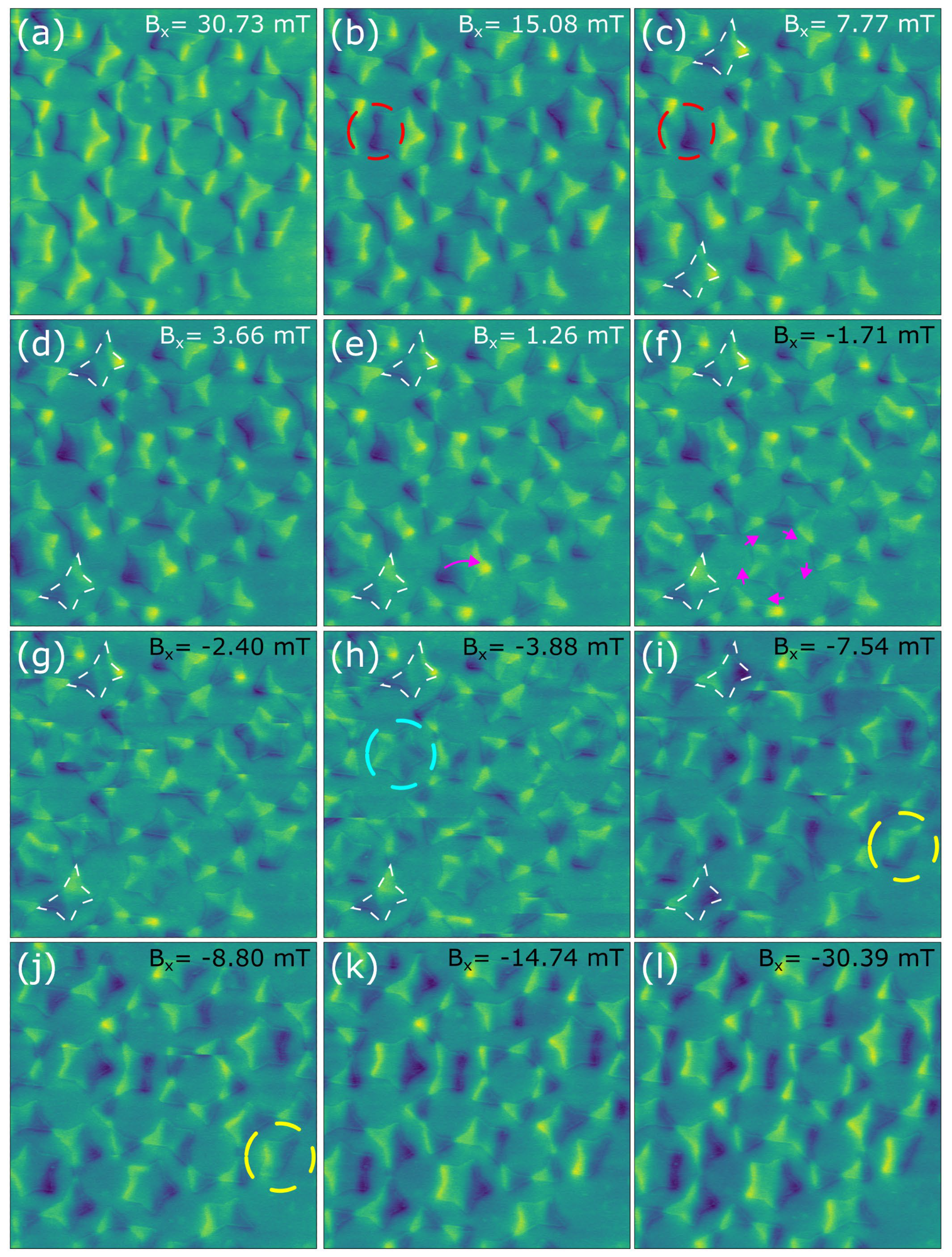
Figure 2. MFM phase images taken at different applied fields while changing from saturation field in one direction to saturation field in another direction (i.e. 31 to -31 mT). Image size: 13×13 μm2. Phase range: 0.3 deg. Image Credit: Nanosurf AG
Observing Figure 2 and monitoring the field evolution from 30.73 to -30.39 mT, it becomes evident that there is minimal change between Figure 2a at 30.73 mT and Figure 2b at 15.08 mT. This suggests that the system is likely approaching the saturating state, and it would necessitate a large field to eliminate the remaining few domain walls within the system.
This is utilized as a starting field, as it likely removed any prior magnetic history. Following the evolution from 15.08 mT to 7.77 mT (as shown in Figure 2c) enables the observation of changes in magnetization (highlighted by the red dashed circle). These changes are anticipated. The bright and dark spots in the MFM image signify the presence of a stray magnetic field emanating from the magnetic nanostructure.
As the external magnetic field decreases, the shape anisotropy energy term increases in weight. In other words, the magnetic domain tends to copy the shape of the nanostructure. The magnetization adjusts to the geometrical constrictions, with sharp edges acting as natural pinning points where either stray fields are created or domain walls become pinned.
Figure 2e shows where domain wall pinning is evident (1.26 and -1.71 mT, respectively). In these figures, the magnetization within the star transitions from what appears to be a single domain (indicated by the purple arrow in e), to numerous domains (indicated with purple arrows in f) aligned with the “spikes” of the star.
It should be noted that a similar star, aligned in the same way with respect to the field, necessitates a significantly different field to switch magnetization (Figure 2h, at -3.88 mT, indicated by a turquoise dashed circle).
This may arise due to the influence of nearby magnetic elements on the local energy landscape. The impact of the local landscape on switching fields is also evident in the case of the starred trapezoids, shown in white from Figure 2c to i (7.77, 3.66, 1.26 -1.71, -2.4, -3.88, and -7.55 mT respectively).
Despite sharing the same orientation in relation to the external magnetic field, their positions in relation to the lattice vary significantly—for example, one is situated at the border.
Some elements, such as the trapezoid located at the border and highlighted by yellow dashed circles in Figure 2i and j, switch magnetization at relatively high fields (compare -7.54 mT in Figure 2i and -8.8 mT in Figure 2j). This suggests the possibility that either the rest of the lattice favors this switch at high fields, or that the lattice favors the rest of the elements that switch at unusually low fields. In either scenario, these elements are essential for assessing the fit of numerical models of the system.
In addition to interactions between the lattice and field interactions, it is crucial to acknowledge that certain transitions observed in Figure 2 result from probe-sample interactions (whenever a horizontal discontinuity crosses the image).
While these interactions are unavoidable, they can be mitigated through the use of different probes to investigate different regimes. For example, probes with low moment are beneficial when a small magnetic field is applied, while probes with high coercivity prove advantageous when applying large magnetic fields.
Summary
In summary, the VMF sample holder enables the investigation of frustrated magnetic systems, exemplified by the artificial spin ice presented here. Understanding the magnetic field necessary to induce switching in specific elements of the artificial spin ice lattice enables the stimulation of its behavior and extraction of ground states.
This information can be utilized to refine the lattice design so that it aligns with the desired behavior, enhancing its applicability for practical applications.
References and Further Reading
- Marković, D., et al., Nat Rev Phys 2, 499–510.
- Grollier, J. et al., Nature Electronics, 3(7), 360–370. -0360-9
- Caravelli, F. et al., New J. Phys. 22, 103052.
- Kazakova, O. et al., J. Appl. Phys. 2019, 125, 060901.
- Corte-León, H. et al., Small 2020, 1906144, 1.

This information has been sourced, reviewed and adapted from materials provided by Nanosurf AG.
For more information on this source, please visit Nanosurf AG.