|
This paper describes the design and characterisation of a long-range capacitive displacement sensor, NanoSensor® model NXE2. Special emphasis is placed on the design features and metrological considerations that facilitate high resolution, very high linearity, high repeatability and low power dissipation at the sensor head. We report on the design, and performance of a new capacitance position sensor, with range of > 3 mm, noise of 2 nm.Hz-½, and 0.003% non-linearity.
Experimental data is presented showing a fourth order polynomial correction, which allows easy correction of the linearity error to 0.003% with straightforward sensor mounting. The sensitivity of the system to installation tilt, temperature and humidity changes is also presented[1][2].
Introduction
Capacitance position sensors have been widely used in high precision displacement measurement. They have the benefit of being non-contact, having zero-hysteresis[2] and low power dissipation at the point of measurement. They are capable of very high resolution: a few picometres being readily achievable. The latest generation of wafer-stepper machines require measurements with a precision of better than 10 nm over distances of a few millimetres.
Most capacitance sensors have a single probe that measure capacitance to a grounded target. However this technique suffers from high thermal drift, typically in the order of 1 µm.K-1 for a sensor with 2 mm range (500 ppm), and requires a low noise ground for high-resolution applications. A two-plate system using a probe and target electrode can overcome these problems.
Description of NanoSensor® System
The simplest form of capacitance micrometer is the parallel plate capacitor. In this configuration the capacitance, C, is given by equation 1 where εr is the relative permittivity of the material between the plates, ε0 is the permittivity of vacuum, A is the plate area and d is the plate separation or gap.
 (1) (1)
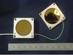
Figure 1. Probe and Target Sensor showing active area (A), guard ring and housing.
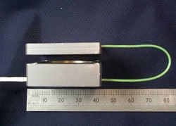
Figure 2. Probe and Target Sensor showing sensor gap (d).
In a capacitance micrometer the values for ε0, εr and A are fixed the plate separation d can be calculated if the capacitance is measured. The drive electronics, situated 5 m away, decodes the signal to an analogue voltage in the range ±10 V, representing a range of 3 mm. Table 1 gives the physical specifications of the NXE2 sensor system.
Table 1. Physical Dimensions of the NXE2 NanoSensor®.
|
|
|
Probe Size
|
35 x 35 x 10mm
|
|
Probe Active Area
|
452(mm2)
|
|
Target Size
|
35 x 35 x 10mm
|
|
Nominal Sensor Gap
|
3.0(mm)
|
|
Sensor Operating Range
|
1.5 to 4.5(mm)
|
|
Cable Length
|
5(m)
|
|
Housing Material
|
Aluminium
|
|
Electrode Material
|
Gold coated Zerodur
|
System Calibration and Experimental Measurements
The NXE2 sensor system was characterised and calibrated using a Michelson Interferometer[4] designed by the National Physical Laboratory (NPL, UK). The interferometer allows one half of the sensor pair, the target, to be fixed in position while the other half, the probe, is moved over the test range, -1.5 mm to + 1.5 mm, using a coarse motor driven stage.
The probe position is measured at 65 different points using the interferometer. The output voltage from the electronic module is also measured at each point to allow calibration of the system. The output from this test is shown in figure 3.
Figure 3. Calibration on the laser Interferometer.
If the residuals from the line of best fit are calculated it becomes obvious that there is non-linearity of ~ 0.4% associated with the system. This can be seen in figure 4. If this linearity error is stable over time and does not suffer from hysteresis or tilt error during installation[2] then this can be corrected using a polynomial fit.
Figure 4. Residuals from line of best fit.
This effect of tilt has been quantified for this system by introducing a known tilt level to the sensor and then re-measuring the linearity error over the 3.0 mm operating range. Figure 5.0 shows that for installation tilt error of up to 4.5 mrad the linearity error remains below 0.02%. This shows that the system is re-configurable and will not suffer from tilt installation error.
Figure 5. Change in measured linearity with installation tilt error.
The non-linearity error does not suffer from tilt and is very repeatable so it can be compensated using a 4th order polynomial fit. Figure 6 shows the position error in a sensor system that has been compensation using the 4th order polynomial.
Figure 6. Residuals from line of best fit after 4th order polynomial compensation.
After the compensation has been implemented the linearity error has been reduced to 0.003%. This is equivalent to 0.10 µm peak deviation over the 3 mm operating range of the sensor [3].
The materials used for this NanoSensor® have been specifically chosen to give high levels of stability with changing temperature and humidity. The aluminium housing was selected to match the metrology frame of the wafer-stepper and to be isothermal in the system. The sensor electrodes have been manufactured from gold-coated Zerodur.
The absolute thermal coefficient of the sensor was characterised by placing the sensors in a spacing jig constructed from Super Invar (TC = 0.3 ppm.K-1). The system was then cycled between 10 and 40°C while the position output from the system was measured. This produced the graph shown in figure 7.
Figure 7. Uncorrected temperature coefficient of the sensor.
This shows the absolute temperature coefficient of the sensor as -0.62 µm.K-1 (206 ppm).
If the measurement is corrected to allow for the use of Super Invar measurement jigs instead of aluminium then the error is reduced to -0.32 µm.K-1 (106 ppm) when the sensor is installed in the system.
Figure 8. Corrected temperature coefficient of the sensor.
The humidity coefficient of the system was measured using the Super Invar jigs placed inside an environmental test chamber. The position output was measured while the sensor was cycled between 70% and 30%. The system relative humidity (RH) coefficient was measured as -95 nm.%-1 (31 ppm).
Figure 9. AZoNano - Nanotechnology.
Conclusions
Conclusions from the design and testing of the NXE2 NanoSensor® have been presented and are summarised in table 2 below.
a. A high resolution NanoSensor® with 3 mm measuring range and linearity error of 0.003 % has been achieved.
b. It has been shown that the system has a low sensitivity to installation tilt.
c. Measurement results have been presented showing thermal drift of -0.32 µm.K-1 (106 ppm) and humidity coefficient of -95 nm.%-1 (31 ppm).
Table 2. Summary of measurement results.
|
|
|
Range
|
3.0mm, 1.5mm to 4.5mm
|
|
Nominal Sensor Gap
|
3.0mm
|
|
Linearity Error (Uncompensated)
|
0.4%
|
|
Linearity Error (Compensated)
|
<0.02%
|
|
Thermal Drift
|
-0.32µm.K-1 (106ppm)
|
|
Humidity Coefficient
|
-95nm.%-1 (31ppm)
|
|
Noise Coefficient
|
2nm.Hz-½
|
|