PeakForce Tapping (PFT) and ScanAsyst (SA) are two Atomic Force Microsocope (AFM) imaging techniques recently introduced by Bruker which fits into the framework of existing AFM modes. The crucial step in AFM is the time-consuming actual adjustment of AFM feedback parameters by the user. ScanAsyst provides consistent expert-quality results independent of user experience.
PeakForce Tapping
PeakForce Tapping, like TappingMode, avoids lateral forces by intermittent contacting of the sample. It differs from TappingMode in that it operates in a non-resonant mode. The benefits of contact and TappingMode imaging are combined in the oscillating system in PeakForce Tapping and unwanted resonances at turnaround points are avoided. The general operation is illustrated in figure 1.
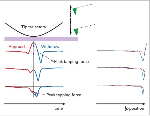
Figure 1. Experimental data of force curves for a cantilever operated in PeakForce Tapping. The lever is driven by a sinusoidal wave and the curves are displayed as force versus time and force versus distance.
The controlled interaction force can be lower due to the higher force sensitivity in a soft cantilever. The typical repetition rate of 2kHz allows for imaging speeds that are comparable to TappingMode operation (figure 2).
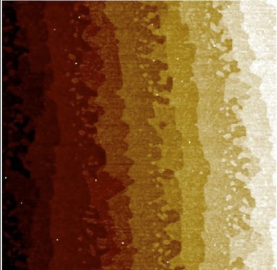
Figure 2. 2μm scan of a sample of graphene obtained in PeakForce Tapping operation. Several monoatomic steps and small islands can be clearly identified.
ScanAsyst
ScanAsyst uses PeakForce Tapping mechanism and adjusts all critical imaging parameters. This gives high-quality images without the user adjusting imaging parameters and the problematic AFM user interfaces. A basic SA interface is shown in figure 3. The user only has to select the actual scan area. There is also an option to set the AutoControl field by individual and choose the parameters.
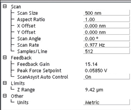
Figure 3. Screen shot of the basic SA interface. All feedback settings and the scan rate are automatically calculated by the AFM.
The underlying calculations enabling SA happens on the fast FPGA chips implemented in Bruker controllers. The noise threshold, the key parameter, is automatically adjusted by the AFM after it has completed a full frame as not all scans require the ultra-low noise that Bruker AFMs can achieve. By selecting a discrete threshold, the AFM can adjust feedback and imaging speed to get a certain result instead of manipulating the feedback loop. The data that SA produces even during first time imaging is better than could be produced by an AFM expert (figure 4).
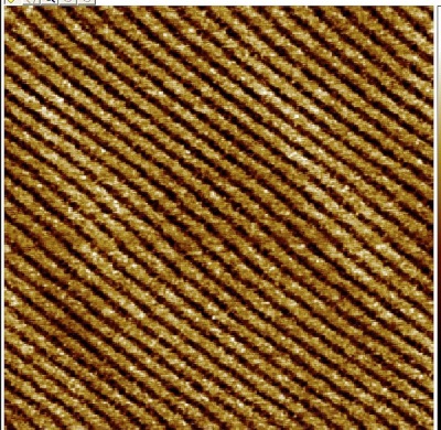
Figure 4. 80nm scan of C18H38 alkane chains obtained in PFT. The inter-lamellar distance is only 2nm!
The built-in flexibility of SA allows users to fully or partially control the PFT operation. An example of an expanded SA user interface is shown in figure 5.
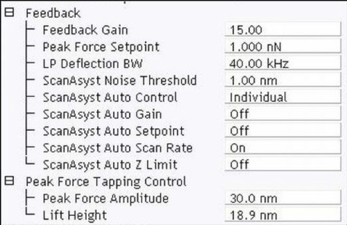
Figure 5. Screen shot of the expanded SA interface. If desired, SA allows flexibility for parameters to be adjusted manually.
During SA/PFT imaging the user can constantly monitor the integrity of operation by looking at the built-in force monitor as shown in figure 6.
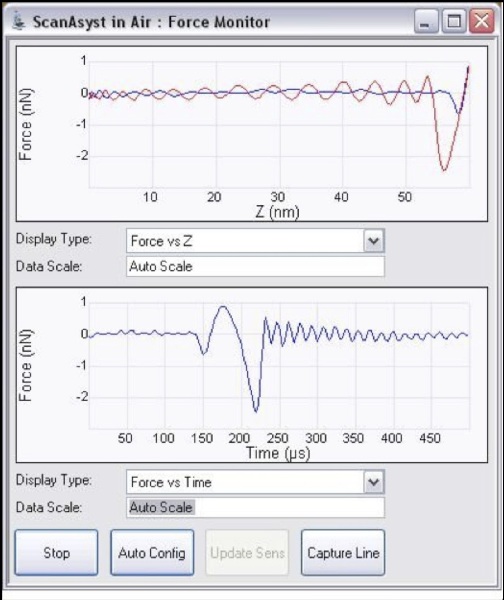
Figure 6. Real-time shot of the force-monitor during imaging with SA. This allows the user to constantly monitor the integrity of the imaging process.
Advantages
The issue of height data in TappingMode is resolved in PFT, since it responds only to short-range interaction as long-range interactions are ignored for height control, a key to high-resolution imaging. By consistently controlling the short-range interaction forces, PFT enables image quality control with fewer artifacts.
Key features PFT are:
- Insensitivity to effects due to resonant system geometry (figure 7)
- Unaffected by Q-factor of cantilever (figure 8).
- Can be operated for changing environments.
- Operated at fixed frequency, hence cantilever tuning unnecessary.
- Re-tuning not required even with temperature or medium change.
- Insensitive to changes in probe resonant frequency and Q as PFT.
- Imaging forces as low as a few tens of pico-newtons are allowed as the SA software subtracts even the background changes caused by temperature or fluid- level fluctuations (figure 9). SA operation at different temperatures is given in figure 10.
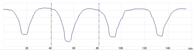
Figure 7. 160nm linescan of steep trenches. The flat bottom indicates that the probe reached all the way.
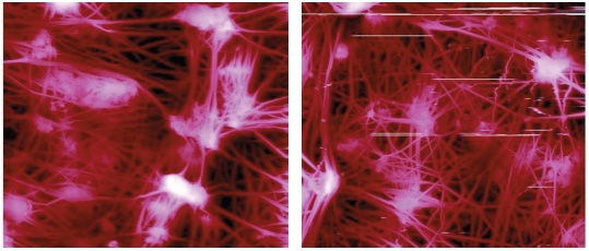
Figure 8. 30μm scan of a Teflon membrane in PeakForce (left) and regular TappingMode (right). Artifacts visible in TappingMode operation are not present in the PeakForce Tapping data.
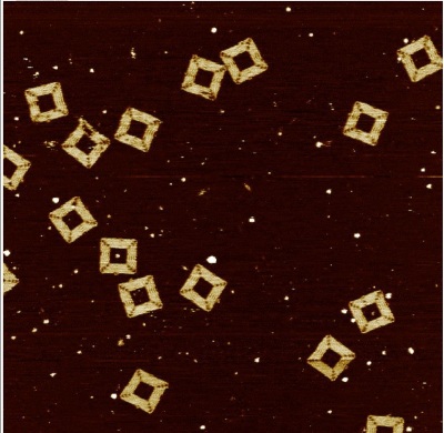
Figure 9. 1μm scan of Origami DNA in buffer solution using SA. Single strands of DNA comprising the square structure are clearly discernible.
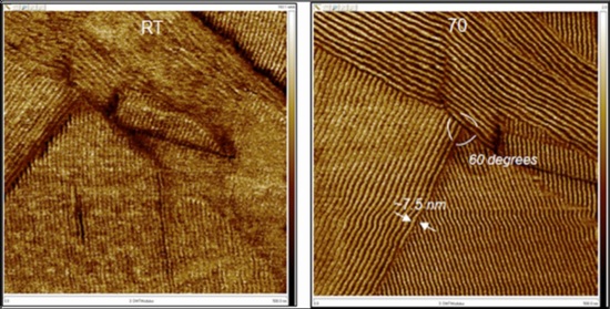
Figure 10. 500nm images of C60H122 at room temperature and 70°C.
The force curves are also available to the user to extract additional material specific information. Bruker uses the capability of obtaining multiple force–distance curves at each image location in its PeakForce QNM package. Figure 11 shows the resulting curves from a HSDC of 100ms and one selected curve.
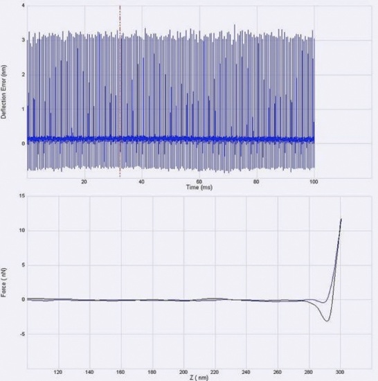
Figure 11. Result of a HSDC during the imaging process. The force curves that enable the imaging can be extracted and also be used for further analysis.
A variety of modes, traditionally carried out in contact mode operation, can greatly benefit from combination with PFT. Electrical modes such as Scanning Capacitance Microscopy (SCM) or Tunneling AFM (TUNA) would get a performance boost. A TUNA image obtained by combining the SA/PFT is shown in figure 12.
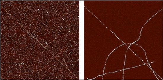
Figure 12. PFT-TUNA image of carbon nanotubes. Sample topography on the left and conductivity map on the right. Sample courtesy of Prof. Hague, Rice University.
Conclusions
Advantage of AFM dominated Tapping is the lack of lateral forces inherent to contact imaging. But its complexity has prevented the automation of the critical step and the feedback loop adjustment has hindered the advancement of AFM This note shows that PeakForce Tapping generate data that is equal and better than TappingMode and the data using ScanAsyst is reliable even if obtained by a new user.
.jpg)
This information has been sourced, reviewed and adapted from materials provided by Bruker Nano Surfaces.
For more information on this source, please visit Bruker Nano Surfaces.