KLA Instruments™ Nano Indenter® G200X and its Zeta-20 optical profiler are ideal for the quantification of changes in the topographic and nanomechanical properties of N95 respirators after these have been exposed to UVC.
The COVID-19 pandemic has seen frontline healthcare workers face a potential shortage of essential N95 face masks. In early 2020, the Centers for Disease Control (CDC) developed recommendations for reusing masks that had previously been considered single use solutions.
However, questions have arisen around how many times these masks can be reused before they lose their protective properties.
The Department of Homeland Security initially projected that the U.S. healthcare system would require – but likely not have access to – up to 3.5 billion N95 filtering respirator (FFR) face masks during the first year of the coronavirus pandemic.
Cleaning and reusing masks can enhance both worker and patient safety, but it is imperative that those frontline workers are clear on how many times N95 masks can be reused without this negatively impacting their efficacy.
The team at KLA Instruments has been working to help answer this question through the use of nanoindentation and imaging.
N95 FFR face masks are generally comprised of several filtration layers, with the inner melt-blown layer widely recognized as the primary functional component.1
This layer’s polypropylene (PP) fibrils undergo changes in nanomechanical strength and topographic structure when exposed to the UVC light commonly used for disinfection ahead of mask reuse.
These changes were quantified using the KLA Instruments Nano Indenter G200X and the KLA Instruments Zeta-20 optical profiler.
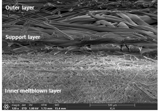
Figure 1. The N95 filtering facepiece respirator (FFR) face mask is typically composed of multiple filtration layers, of which the inner layer is the key functional component. This layer is made from meltblown non-woven fabric, which is composed of thousands of very thin, noncontinuous fibrils. Polypropylene (PP) is the most widely used raw material for the meltblown fibrils due to its low melting point. Image Credit: KLA Corporation
UVC Exposure and Its Use as a Disinfectant for N95 Respirators
In order to ensure effective decontamination, the necessary UVC dose at the inner mask layer is several hundred-fold higher than the dose required for virus inactivation in the air or on surfaces.
This process may lead to polymer degradation, posing a risk of damage to the N95 respirator materials following multiple decontamination cycles.
Bursting strength tests have been conducted using N95 structures comprised of tangled and spun-bonded polypropylene fibers. These tests showed that UVC treatment radically decreased the strength of N95 layers.2
With these factors in mind, properly understanding the effect of UVC on the nanoscale physical properties of the individual fibers is crucial.
UVC Exposure of Respirator Mask Samples
In one such case study, a 3M 9211+ N95 respirator mask was cut into 1cm square coupons before being placed into an SEM. The coupons were exposed to UVC light, resulting in a total of five cumulative exposure samples.
Fiber samples were scanned using the KLA Nano Indenter G200X NanoVision option. This robust instrument includes a closed-loop nanopositioning stage, enabling high resolution 3D imaging and precise targeting designed to facilitate characterization of the individual phases of complex materials.
NanoVision allows researchers to investigate residual impressions, enabling the quantification of a range of material response phenomena, including deformation volume, fracture toughness and pile-up.
Nanoindentation testing in this case study was performed using the CSM option and an InForce 50 actuator equipped with a Berkovich indenter.
Young’s modulus and hardness are measured as a continuous function of penetration when using the CSM option.3 The InView test method Advanced Dynamic E and H was employed to generate results.
This method is suitable for the measurement of Young’s modulus and hardness in small volume materials, for example, PP fibers.
Mask Fiber Mechanical Properties Analyzed Using the KLA Nano Indenter G200X
Figure 2a displays a 16 µm x 16 µm scanning probe microscopy (SPM) image of an untreated meltblown microfiber. This was taken prior to nanoindentation and was generated via NanoVision scanning on the KLA Nano Indenter G200X.
Three nanoindentation tests were conducted on the fiber, performed under maximum loads of 0.1 mN, 0.3 mN and 0.5 mN, respectively.
Figure 2b displays the SPM image of the fiber following indentation. This image displays the three residual indentation marks. Load-displacement curves for each of the three tests are displayed in Figure 2c, with the line color for each of the curves corresponding to mark indicators in Figure 2b.
Different residual displacements were generated as indentation elastic recovery was investigated on the unloading segments. Using the 3D SPM image, the residual indentation size and depth were also measured based on the surface profile along the longitudinal axis of the fiber.
Figure 2d shows residual depth measurements where loads of 0.1 mN, 0.3 mN and 0.5 mN resulted in residual indentation depths of 57 nm, 107 nm and 147 nm, respectively.
This was consistent with established indentation load and depth curves. The inset image shown in Figure 2d displays the profile location along the fiber.
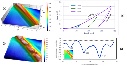
Figure 2. (a) NanoVision SPM image of a PP fiber prior to nanoindentation testing; (b) same fiber after nanoindentation testing, with residual indentation marks highlighted; (c) load-displacement curve for the three indentations; and (d) PP surface profile along the fiber, showing measured indentation depth. Image Credit: KLA Corporation
Examination of Polyproylene Fibers Using the Zeta-20 Optical Profiler
The fibers’ width measurements and topography were acquired using a KLA Zeta-20 optical profiler.
The Zeta-20 employs proprietary ZDot™ technology to deliver effective non-contact 3D topographic measurement, allowing the user to rapidly explore large sample areas in order to find smaller regions of interest suitable for further analysis.
As compared to a scanning electron microscope, the Zeta optical profiler offers True Color 3D imaging while being quick and easy to operate.
The instrument requires minimal sample preparation, avoiding sample damage, outgassing and/or contamination resulting from the SEM measurement itself.
Because this method is non-contact and non-damaging, it allows further metrology techniques such as Raman spectroscopy and FTIR to be applied to the same sample, providing additional analysis data without concern that the previous metrology could have chemically or physically altered the sample.
The ZDot structured illumination imaging mode was utilized within this study in order to produce 3D True Color images for measuring the PP fiber width.
Figure 3 displays a Zeta-20 True Color 3D image of the untreated N95 respirator meltblown layer, revealing that the untreated fibers seem to be of variable size and shape. The fibers appear tangled, with some joining together to form large bundles.
Figure 4 displays two Zeta-20 images of the N95 respirator meltblown layer topography. These are displayed for both untreated samples and a sample following a UVC dose of 19 J/cm2, with height variation represented by color.
Fibers appear wider and more bundled without UVC exposure, with voids between the fibers appearing smaller than those in the UVC-treated samples. At 19 J/cm2, however, fibers demonstrate a notable decrease in width alongside increased separation.
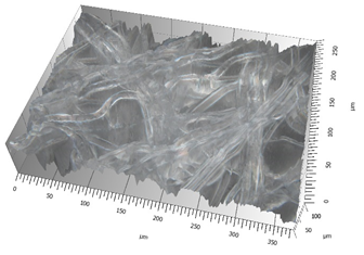
Figure 3. Zeta-20 image of the N95 respirator meltblown layer with no UVC treatment. The untreated fibers appear to be tangled and variable in size and shape, with some fibers joining to form large bundles. Gray level variation is due to translucence of the sample fibers and the dark sample mounting surface. Image Credit: KLA Corporation
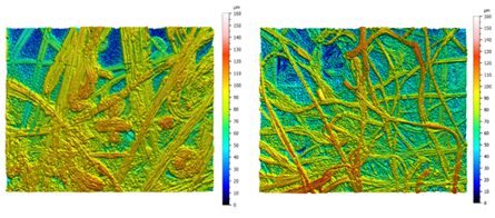
Figure 4. Zeta-20 images of the meltblown layer of the N95 respirator with different UVC doses: (a) 0 J/cm2, and (b) 19 J/cm2, where the decrease in average fiber width is clearly shown. Z scale is 0–160 µm for both images and field of view is 374 µm x 281 µm. Image Credit: KLA Corporation
Comparing Nanomechanical and Topographic Properties for N95 Respirator Fibers
Hardness, Young’s modulus and fiber width were each obtained from PP fibers that had been exposed to various cumulative doses of UVC light. Young’s modulus is a measure of material stiffness, while hardness is a function of the maximum applied load and any resulting plastic deformation occurring in the material.
Figure 5 shows the results of physical changes to the fibers at higher doses. These results confirmed that the longer the mask samples were sterilized, the greater the resulting changes to the mask’s topographic and nanomechanical properties.
Hardness, Young’s modulus and average fiber width were found to decrease as the UVC dose increased. The fiber width showed a robust logarithmic decrease as dose increased.
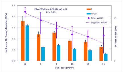
Figure 5. Hardness (H), Young’s Modulus (E) and fiber width are shown as a function of cumulative UVC dose for N95 polypropylene fibers. The fiber width displays a strong logarithmic decrease with increase in dose. Image Credit: KLA Corporation
Conclusions
COVID-19 cases continue to pose a serious challenge to large parts of the U.S., with frontline workers likely to be asked to reuse personal protective equipment such as N95 masks. It is imperative that frontline workers know how often they can safely disinfect and reuse these masks in order to ensure their overall protection.
The team at KLA Instruments employed a range of tests to verify that N95 respirators’ inner filtration layer loses strength when these are exposed to accumulated doses of UVC radiation.
This resulting loss of fiber strength may cause small tears or holes to appear in the mask, therefore resulting in reduced protection against COVID-19. The decreased fiber width may also provide openings, allowing the virus to penetrate the mask and reach the wearer.
More details of the study can be found in the article titled “Effect of Ultraviolet C Disinfection Treatment on the Nanomechanical and Topographic Properties of N95 Respirator Filtration Microfibers,” published in the September 2020 edition of MRS Advances.
References
- "Respirator Trusted-Source: Selection FAQs," U.S. National Institute for Occupational Safety and Health, 2020-03-12.
- W.G. Lindsley, S.B. Martin, R.E. Thewlis, K. Sarkisian, J.O. Nwoko, K.R. Mead and J.D. Noti, J. D., “Effects of Ultraviolet Germicidal Irradiation (UVGI) on N95 Respirator Filtration Performance and Structural Integrity,” Journal of Occupational and Environmental Hygiene, volume 12 (8), (2015) 509–517, https://doi.org/10.1080/15459624.2015.1018518.
- J.L. Hay, P. Agee and E.G. Herbert, “Continuous stiffness measurement during instrumented indentation testing,” Experimental Techniques, volume 34 (3), (2010) 86-94.

This information has been sourced, reviewed and adapted from materials provided by KLA Corporation.
For more information on this source, please visit KLA Corporation.