One of the common modes of scanning probe microscopy (SPM) is Magnetic force microscopy (MFM). As indicated by the name, SPM is used to map magnetic properties.
On the nanoscale, MFM probes local magnetic fields, producing images that include information on a sample’s localized magnetic properties as well as the mapping of magnetic domains and walls.
SPM is principally a comparative, contrast-based technique that has extensively been used to characterize magnetic storage media, magnetic nanomaterials, superconductors, and even biological systems.
In addition to single point measurement at localized regions of interest, SPM can also achieve maps of force curves. This facilitates the correlation of localized mechanical property information with topographical or other information acquired by the different imaging methods.
How does it work?
MFM functions in dynamic force mode with phase contrast. Where a 180° phase shift going from below to above the resonance frequency is present, a cantilever with a thin magnetic coating is driven close to its resonance frequency f0.
Standard resonance frequencies are in the tens to hundreds of kilohertz. As the cantilever passes over the sample at a predetermined height, the MFM maps the phase of the oscillation. An attractive magnetic force gradient is acquired when the magnetic junctures of the tip and sample are parallel.
This allows the resonance curve to shift a lower frequency, alongside a decrease in phase shift at the excitation frequency, as shown in Figure 1.
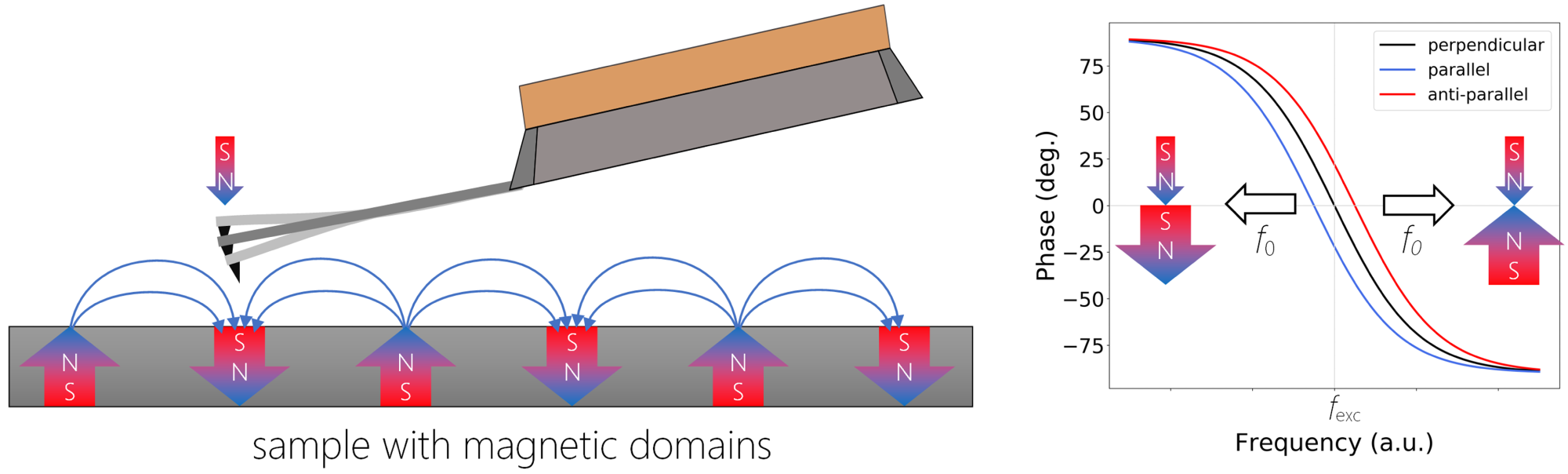
Figure 1. A schematic representation of MFM. If the local magnetic moments are parallel, i.e. magnetic field in the sample is aligned in the direction of the tip magnetization, there is an attractive force causing a negative phase shift (blue curve), in the anti-parallel orientation (red curve), the repulsive force causes positive phase shift from the excitation frequency fexc. There is no shift in case when the magnetic fields of tip and sample are perpendicular to each other. Image Credit: Nanosurf AG
Alternatively, a repulsive magnetic force gradient by anti-parallel orientation of the magnetic moments will generate a shift in the resonance curve to a higher frequency, together with an increase in phase shift at the excitation frequency. The cantilever largely responds to out-of-plane fields.
Magnetic forces that act on the cantilever by the sample are quantified as the tip is moved away from the surface, hence partitioning the long-range magnetic forces from the short-range atomic forces between tip and sample.
The tip-sample distance is a vitally important parameter to optimize for efficient MFM operation. If the tip is too close to the sample, the topography will be scrambled into the MFM signal, considerably complicating its interpretation. If the distance between tip and sample is too great, the resolution will be jeopardized.
As with all SPM-based methods, the main factor in MFM is the magnetized probe. The silicon-based probes, covered with various thin magnetic layers, such as cobalt alloys, are commercially available. A range of MFM probes can be acquired, including those that are high-moment, low-moment and low coercivity.
MFM can function in either a single- or dual-pass mode: the MFM tip passes over the sample at a constant height throughout single-pass mode. To maintain a constant gap, the user should compensate for a slope between the sample and the scanner.
This introduction of MFM is the fastest and significantly reduces tip wear. Since the topography is not measured, the tip sample distance cannot be maintained at a constant.
Consequently, the lift height must be set by the highest areas of the sample to avoid topography convolution in these higher parts. This leads to a degradation in resolution and contrast.
During dual pass mode, the cantilever passes over each line in the image twice. In the course of the first pass, the MFM tip accumulates topography information in dynamic mode. The user then lifts the tip over the sample surface for the second pass by a predetermined amount.
Throughout the second pass, the tip traces the contours of the topography, maintaining a constant tip-sample distance during every scan line. The second scan’s amplitude can be reduced to get closer to the surface than the first topography recording scan.
To achieve complete optimization, the tip must be as close to the sample as possible but not too close as to collide with the sample.
Applications
Magnetic Tape
The investigation of magnetic storage media, which have nanoscale features that cannot be imaged with alternative techniques, is one of the most common applications of MFM.
MFM is used extensively for quality control in this industry because it can identify defects and feature morphology essential for optimizing device performance.
As shown in Figure 2, the AFM image serves as an example from the data storage industry of a digital backup tape with magnetically stored data.
The 50 x 50 μm2 image clearly indicates the magnetized domains of data stored on this magnetic storage tape. This sample is straightforward and can be used to get familiar with the MFM operation mode.
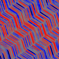
Figure 2. Magnetic force microscopy of digital backup tape with magnetically stored data. Scan size: 50 x 50 µm2. Image Credit: Nanosurf AG
Hard Disk Drive
Arguably the most frequently used application of MFM on magnetic storage devices is the measurement of hard disk drives. In Figure 3, AFM and MFM are utilized to effectively analyze a hard disk drive.
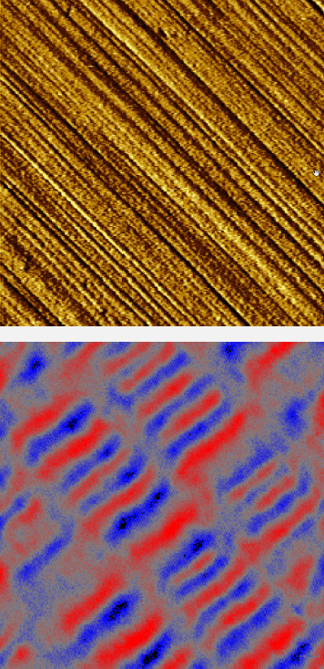
Figure 3. Magnetic force microscopy of hard drive with magnetically stored data. Scan size: 2 x 2 µm2. Image Credit: Nanosurf AG
Images of 2 x 2 µm2 are displayed with the topography image at the top and the MFM phase image at the bottom. Acquired in dynamic force mode, the topography image displays diagonal grooves parallel to the recording tracks.
However, the topography does not disclose any of the magnetization information, which is obvious in the equivalent MFM phase image. The red and blue areas in the MFM image depict magnetic domains, where red signifies repulsive forces and blue for the attractive forces acting on the tip.
A track distance of ~600 nm with a bit length of ~70 nm can be inferred, a length scale that can only be imaged by an approach such as scanning probe microscopy.
MFM on Steel
In the materials science sector, MFM is used for the visualization of magnetic domains, as displayed in Figure 4. Polished stainless steel possesses a rich morphology of various domains.
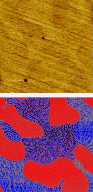
Figure 4. Magnetic force microscopy of a steel sample with 2 different magnetic phases. Scan size: 80 x 80 µm2. Image Credit: Nanosurf AG
An 80 x 80 µm2 topography image is displayed on the top, exposing a number of polishing scratches and perhaps the suggestion of some underlying morphology in the form of round dark domains.
The analogous MFM phase image, acquired in dual pass MFM, demonstrates a far greater and complete understanding of the polished steel surface, uncovering domains with low MFM contrast (red) and domains with a particular wormlike contrast scattered across the red domains.
The red domain constitutes the paramagnetic austenite phase that shows uniform contrast, while the wormlike domain signifies the ferrite phase as a result of its ferromagnetic behavior. The pattern and contrast of the wormlike domains are dependent on the magnetic field’s orientation.
Thin Permalloy Films
As a technique for visualizing magnetism in various materials, MFM is also highly appropriate for the imaging of magnetic domains in thin ferromagnetic films.
In this instance, permalloy (Fe0.2Ni0.8) is known for its exceptionally high magnetic permeability. In the 30 x 30 µm2 image of Figure 5, the remnant magnetization of the film is observed where the domains of opposing orientations construct a pattern of stripes with a period of ~0.5 µm.
Figure 5. Magnetic force microscopy of thin permalloy film with stripe domains. Scan size: 30 x 30 µm2. Image Credit: Nanosurf AG
The period of the pattern is dependent on the magnetic properties of the film and it rises with the square root of its thickness.
Conclusion
Magnetic force microscopy, a relative of atomic force microscopy, is able to detect the tip-sample magnetic interactions to remodel the magnetic structure of the sample. In spite of MFM primarily being a qualitative technique, it has been demonstrated to be an exceptional characterization tool in industrial and research applications.
MFM has been used extensively for the characterization of magnetic nanostructures and imaging the magnetic field distribution. The main advantages of MFM are its high spatial resolution and sensitivity, capacity to operate in various environments and the ability to apply in situ magnetic fields to investigate magnetization processes.

This information has been sourced, reviewed and adapted from materials provided by Nanosurf AG.
For more information on this source, please visit Nanosurf AG.