Jun 8 2010
The electrical resistance of solid state materials is measured by means of well-known established methods. However, for liquid solutions this problem is not so trivial, its solution being very important especially for processes at which the electric field is a driving force. For example, during the fiber electrospinning, the high-voltage-pull-out force strongly depends not only on the liquid precursor's viscosity and polarity, but also on its Ohmic resistance.
An express experimental method is developed in Central Laboratory of Photoprocesses, which reveals the possibility to measure precisely the Ohmic resistance of different electrospinning precursors for preparation of non-woven mats from micro- and nano-fibers. For this purpose a covered glass electrochemical cells is used with parallel flat platinum electrodes fixed to cell cap. The distance between both electrodes l and S - their area, define the cell constant A = l/S, which is important for evaluation of the specific conductivity ƒÐ. Its value could be calculated using the Ohm low relation ƒÐ = A/Rx, where Rx is the resistance of the liquid electrolyte.
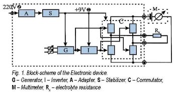 The principle electronic device scheme is presented.
It should be noted, that the simple direct current (DC) method for resistance measurement is not possible to be applied in the case of liquid electrolytes since the precursor polarization, as well as electrolysis occur in the vicinity of the electrodes. To avoid this problem a modification of the Kolrausch alternating-current method is proposed, the voltage frequency being low enough in order to neglect the reactive resistance - either inductivity or capacitance. In principle this is quasi-DC bridge method used previously by our resistance measurements of solid electrolyte thin films from silver halogenides or chalcogenides. It is based on periodic polarity change of the applied DC-voltage at very low fixed frequency, thus avoiding the effects of polarization and electrolysis. The experiments are realized via especially designed compact electronic device assembled of two blocks: Power supply and Commutator.
The power-supplying block is constructed of two different units - Adapter and Stabilizer. Generally, its function is to produce stabilized direct voltage of 9V for the second block - the Commutator. The Adapter unit consists of standard elements: reducing transformer, double-semiperiodical bridge rectifier and filtering condenser. The Stabilization unit is based on integral stabilizer, type 78L09. Three units are incorporated in the Commutator block - Generator, Inverter and Commutator. The Generator unit is designed from an integral scheme and timer, type 555, operating in auto-generation regime. Its function is to produce the initial signal controlling the last unit - the Commutator. This signal has to possess logical command levels. The Generator design allows to regulate the output voltage frequency, as well as the time intervals in which the voltage value is high or low respectively. This permits to use the Commutator for resistance measurements of electrolyte solutions with different polarizability as dependent on the value and the polarity of the potential supplied to each of both electrodes. The frequency change of commutation is foreseen in the range 0.5 − 40 Hz. It is fixed at 12 Hz in the present control measurements for evaluation of the method reliability.
The Inverter unit is constructed as transistor device attended to give an inverted Generator signal on its output. The Commutator unit is a bridge scheme of four analogous keys, ruled in pairs by the outlet signals from the Generator and Inverter, respectively. The electrochemical cell with the studied solution, which resistance is Rx, is incorporated into one of the bridge diagonals, until the measurement device, a digital multimeter, is pluged in the another one. If the multimeter is switched-on in resistance measurement regime, an additional source of DC voltage is applied and a DC current passes through the solution, thus leading to electrolyte polarization in the vicinity of Pt electrodes. However, this polarization is avoided when the polarity of applied voltage periodically changes. The Commutator unit is based on an integral scheme, type 4066, consisted of four MOS analog keys, each of them with resistance about 100 Ħ. These values are commensurate with the resistance of the tested electrolytes - between 20 and 2000 k Ħ and their proportion guaranties } 1% experimental error of the measured values. The voltage polarity could be changed by successive periodic unclog of the opposite key pairs in the bridge, which does not influence the multimeter measurements.
The Ohmic resistance of different inorganic and organic electrolytes is measured with the designed electronic device in order to check the reliability of the method developed. The conductivity data are not calculated in the commonly [ƒ¶ -1.cm-1] unit but in the more used in the electrochemistry [S.m-1] and its derived units. The values obtained for various solutions are presented in Table. It is clearly seen that ƒÐ of different measured electrolytes varies about two orders of magnitude. The literature data for 8 % poly(vinyl) alcohol (PVA) solution are also given for comparison. It could be noted, that a good coincidence between our experimental results and this reference value exists, since the molar weight of PVA differs a little bit from this one of the material used in our control experiments. Besides, the multimeter reads always stable resistance values although they are displayed in "pulsed regime" with frequency of 1-2 Hz. Nevertheless, it is not observed any polarization of the tested electrolytes even during Rx measurements as long as some ten minutes.
Finally, it should be mentioned here that the method proposed and the especially designed compact electronic device allow express Ohmic resistance measurements of inorganic, as well as organic liquid electrolytes. Nowadays it is applied as a routine procedure for permanent resistance control of many electrospinning precursors used for preparation of non-woven mats of micro- and nano-fibers.
Source: http://www.bas.bg/