Microspheres have a wide range of uses in modern life. For example, the density of manufactured materials is lowered using hollow microspheres. In present-day liquid chromatography, the analyte is pushed through a column packed with glass microspheres, which causes the analyte components to separate depending on the speed at which they can traverse the column. In the case of electronic packaging, flexible and reliable connections are created by packing metalized polymer microspheres together. The glass microspheres that were tested in this work were added to paints in order to improve appearance and mar-resistance. In all these applications, a major aspect of design is to understand the microspheres’ mechanical properties.
With relatively slight changes in test procedure and hardware, the inForce 50 actuator turns out to be a general small-scale compression testing system. In this example, the actuator was fitted with a flat-ended punch so as to set up a test condition which can be examined as a double-sided Hertzian contact [1]. Figure 1 shows the test geometry where the Young's modulus, E, is related to the compression force, P, particle diameter, D, and the total compression distance, α, as1:
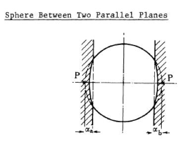
Figure 1. Compression of a sphere between two platens, analyzed as a double-sided Hertzian contact [1]. In this work, the face of the flat punch is one platen and the substrate is the other.
| (1) |
 |
The oscillation aspect of the inForce 50 [2] offers an experimental benefit in that one can use a derivative form of Eq. 1 (S = dP/dα) which shows a more immediate relationship between the measured parameters and properties.
| (2) |
 |
To put it simply, the Young's modulus is related to the compression distance α, and the instantaneous stiffness S. Eq. 2 is less sensitive to the usual measurement errors in the absolute values of α and P and can also show the changes in modulus brought about by increasing compressive strain. This is especially significant for polymer spheres, because the compression process makes the polymer chains to stretch and thus become more densely packed, which can manifest as an exact increase in modulus. This means, when compared to the original microsphere, the compressed polymer microsphere usually has a higher modulus. Therefore, Eq. 2 is a better model, but it can only be applied with testing instruments that overlay an oscillatory force on the semi-static compression process.
A simple definition of strain was used to normalize results for particle size,
| (3) |
 |
and report modulus for individual microspheres at a specific strain value.
Experimental Method
KLA's NanoFlip, which also includes an inForce 50 actuator, was used to perform all the tests. The NanoFlip was selected because its tiny size enables testing within an SEM chamber, and its excellent positioning capability facilitates motion control with nanometer-scale precision. With the help of a tip extender, the actuator was configured and fitted with a conductive diamond frustum (φ = 60°, R = 5 µm). As shown schematically in Figure 2, the entire testing system was placed within the main chamber of a Philips XL 30 Scanning Electron Microscope to enable imaging and testing at the same time.
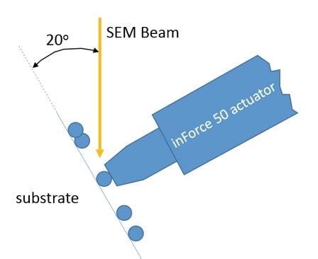
Figure 2. Schematic of test set-up.
Solid microspheres produced from recycled soda-lime glass (mean diameter of 4 µm) were obtained from Prizmalite Industries, Inc2. Ethanol was used to disperse microspheres on a glass microscope slide. The test method "InSEM Dynamic Spherical Compression" was employed to perform all the tests. It operates in individual mode, enabling the user to perform one test at a time. For each test, the following steps were carried out:
- Guided by a video stream from the SEM, the moving platen (the flat face of the diamond frustum indenter) was centered over the particle of interest, about 2 microns above the top of the particle.
- A high-quality SEM image was used to measure the particle’s diameter.
- The moving platen approached the particle at a velocity of 50 nm/seconds until the detection of contact.
- The particle was loaded at a rate of 0.1 mN/seconds while concurrently oscillating the moving platen at a frequency of 100 Hz and an amplitude of 2 nm. When the applied force exceeded 50 mN or the total compression exceeded 1500 nm, loading was terminated.
- The particle was unloaded over the course of 1 second. During the loading and unloading process, fast-scan video4 from the SEM was automatically obtained and synchronized with the mechanical data in InView software.
Results and Discussion
Shown in Figure 3 are the SEM images of the first microsphere, before and after testing (other microspheres show similar deformation). As indicated by the flattened shape and fracture, the test apparently causes both plastic yield. While the aim of this work is to calculate Young's modulus, future efforts will focus on determining yield strength through a similar test.
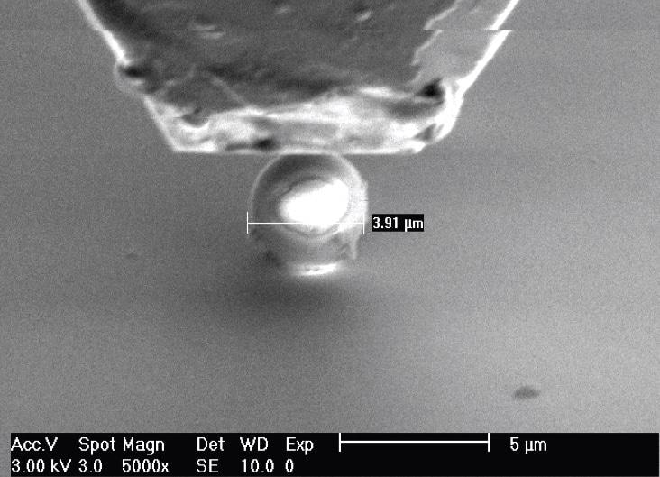
Figure 3a. Microsphere 1, before testing.
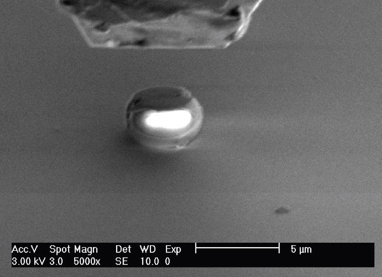
Figure 3b. Microsphere 1, after testing. Particle has both yielded plastically and fractured.
When superimposed oscillation was applied during loading (1 nm, 100 Hz), it produces a continuous measure of stiffness as each microsphere is compressed. Based on this continuous measure of stiffness, modulus is determined according to Eq. 2. This calculation of modulus, as a continuous function of strain for all tests, is shown in Figure 4. As anticipated, the measured modulus is observed to be more consistent from one test to another at larger strains. This is because when the overall compression distance increases, inaccuracies in the compression distance (which occur mainly from imperfections in the shapes of the contacting surfaces) become relatively insignificant. All particles fail at a strain just above 0.3% and therefore, the measured modulus is reported at a lesser strain around 0.20% (between the "X" and the green circle shown in Figure 4).
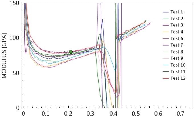
Figure 4. Modulus as a function of compressive strain for twelve microspheres. Failure is obvious at strains just greater than 0.3%.
Figure 4 shows a practical advantage of the superimposed oscillation: simplicity in testing. In order to plan a good test, it is not essential to know much about the sample or its predicted behavior. The superimposed oscillation provides properties as a continuous function of strain (or depth, or load) and the experimenter is free to decide, after the fact, the perfect conditions for reporting properties—in this case, just before fracture. The InView software makes these advantages available to the experimenter by enabling changes in data analysis after the completion of test.
The measurements of diameter and modulus for all microspheres are summarized in Table 1. Even for this small (and not random) sampling, the mean diameter is close to that reported by the manufacturer (4 µm). The measured modulus of 73.6 GPa is found to be within the range of what one should expect for soda-lime glass (72-74 GPa [3]).
Table 1. Summary of diameter and Young’s modulus for soda-lime glass microspheres.
| Microsphere |
Particle Diameter, µm |
E @ 0.25% strain, GPa |
| 1 |
3.91 |
74.44 |
| 2 |
4.31 |
77.16 |
| 3 |
5.44 |
75.57 |
| 4 |
3.12 |
68.20 |
| 5 |
4.34 |
71.36 |
| 6 |
2.79 |
67.31 |
| 7 |
3.55 |
80.01 |
| 8 |
7.40 |
67.29 |
| 9 |
2.89 |
75.24 |
| 10 |
2.92 |
70.75 |
| 11 |
2.89 |
76.38 |
| 12 |
2.92 |
79.80 |
| Median |
3.34 |
74.84 |
| Mean |
3.87 |
73.63 |
| Standard Deviation |
1.32 |
4.32 |
Conclusions
KLA's NanoFlip nanoindenter is used as a general micro-scale compression tester to determine the Young's modulus of glass microspheres measuring approximately four microns in diameter. The test is interpreted with a double-sided Hertzian model so that a value for Young's modulus can be achieved. This testing system measures elastic stiffness as a continuous function of compression, and its dynamic aspect reduces sensitivity to imperfections in the shapes of the contacting bodies, thus enabling an exact measurement of Young's modulus (73.6 ± 4.4 GPa).
1 Assuming infinitely stiff platens.
2 Prizmalite Industries, Inc. 380 Lexington Ave, 17th Floor, New York, NYU 10168. Product Name: P2011SL Glass Microspheres; Lot Number: PS130803A.
3 16.7 ms/line, 2904 lines/frame
4 1.68 ms/line, 484 lines/frame
References
- M. J. Puttock, E. G. Thwaite. "Elastic Compression of Spheres and Cylinders at Point Contact and Line Contact." National Standards Laboratory Technical Paper No. 25. CSIRO, Melbourne, (1969).
- Oliver, W.C. and Pharr, G.M., "An Improved Technique for Determining Hardness and Elastic Modulus Using Load and Displacement Sensing Indentation Experiments, Journal of Materials Research 7(6):1564-1583 (1992).

This information has been sourced, reviewed and adapted from materials provided by Nanomechanics, Inc., a KLA-Tencor company.
For more information on this source, please visit KLA.