|
Nowadays the design of energy sources able to power portable devices like cellular phones, laptop computers or nomadic sensors networks is a challenge. These devices are presently powered with batteries that limit their autonomy and require human intervention and electrical energy sources to recharge. Moreover they generate wastes incompatible with their proliferation. In the next 10 years the international technology roadmap for semiconductors [1] forecasts a decrease of the voltage required to power the working of microcircuits toward 0.6 V. The use of miniature fuel cells (FC) appears an attractive way to power portable electronics with a clean and refillable energy source. This is one of the reasons to explain the intense activity presently occurring in the FC research field. Among all kinds of FC only two are really suitable for miniaturization. The limitation principally comes from the working temperature required to be lower than 100°C. One of them is the proton exchange membrane (PEM) FC. A key element of a PEM FC is the membrane that must have high conductivity for protons and be impermeable to all other present species (H2, O2, water, any other fuel, etc).
State-of-the-art miniature FC [2-6] generally use ionomer films to conduct protons from the anode, where hydrogen is consumed, to the cathode producing, with the reduction of oxygen, water, electrical current and heat. At the present time, the best conductivity (0.08 S.cm-1) is reached by Nafion® perfluorosulfonated membranes. However the high cost and the geometric instability during hydration are only some of the severe constraints of such polymers.
The nature of the proton conductive process in an ionomeric membrane such as Nafion® is not still completely understood. The present consensus [7] is to describe a Nafion® membrane as a skeleton of hydrophobic chains including connected hydrophilic domains containing water molecules. The diameter of the connecting channels is about 3 nm. The low stiffness of this skeleton is responsible for the swelling of the membrane with hydration in response to the molecular interactions.
Here, a potentially disruptive technology is demonstrated that allows a new way to realize the protonic conduction function in a small size FC.
Methods and Materials
The idea developed in this work is to try to reproduce the molecular structure of Nafion® films using harder inorganic materials. To be fully compatible with microelectronics processes and standard microfabrication techniques the FC will be integrated on silicon substrates. The membrane is then made of porous silicon (PS) and direct grafting of proton conducting molecules on the surface of the pores ensures the required conductivity.
The first stage is the realization of the silicon membranes using classical photolithography and wet chemical etching in KOH of (100) oriented silicon wafers. Masking is obtained with a sputtered Cr-Au layer (Cr layer of 15 nm thick and Au layer of 800 nm thick). A previous thermal oxidation of the silicon wafer ensures the electrical insulation of the membrane. The membranes thickness is fixed to 50 µm by adjusting processing time and temperature. Collective processing allows us to obtain simultaneously 69 membranes on a 4” wafer.
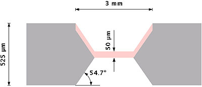
Silicon membranes are then made porous, in a second stage, by anodization in a double-tank cell [8] conceived by AMMT GmbH and consisting of two half-cells in which Pt electrodes are immersed. The silicon wafer separates and isolates the two half-cells. The electrolyte used for anodization is an ethanoic-HF solution (50 % of pure ethanol and 50 % of a 48 % HF solution). Anodization is carried out in the dark at constant current. With phosphorus-doped 0.012-0.014 ohm.cm n+ -type silicon wafers and a current density from 18 to 36 mA.cm-2, we obtain pores from 6 to 10 nm diameter and a porosity of about 50 % [9]. A cross section of the porous silicon membrane obtained is sketched on the figure 1.
|
|
|
Figure 1. Schematic cross-section view of the porous silicon membrane. Silicon is in grey, porous silicon is in pink.
|
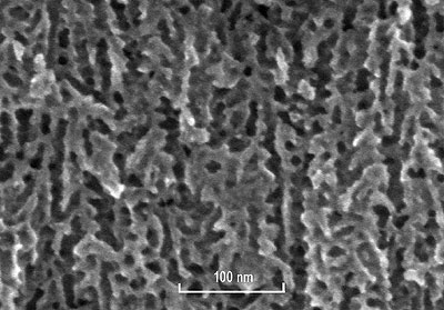
The previous deposition of the Au layer allows the localization of the porosity on silicon membranes during anodization. Indeed a simple LPCVD Si3N4 layer generally used as the masking layer for localized PS (see for example [10]) would not allow lengthy anodization as precious metals (Au, Pt and Ag) allow. The silicon oxide layer under the Cr-Au layer avoids any parasitic formation of PS with the possible internal current generated between silicon substrate and the metallic layer [11]. Once anodization is achieved, membranes are rinsed into an oxidizing bath (Le Vert decontamination solution from Prevor) neutralizing the HF solution. Then several deionized water baths and isopropyl alcohol are used for rinsing and reducing stress into pores. Membranes are finally dried in ambient air. PS membranes with a silica surface layer are obtained. The characterization of these porous membranes is made by FESEM (Field Effect Scanning Electron Microscope) imaging and a typical view of the cross section of the membrane is represented in figure 2.
|
|
|
Figure 2. FESEM cross section view of a n+-type porous silicon membrane. Channels have an average diameter of 10 nm.
|
As proved by conductivity measurements [12] and FESEM imaging, only a few channels are totally opened with this anodization process. Indeed due to the inhomogeneity of the wafer thickness, when the first channels open on the back side of the membranes, the current goes through these opened pores and the anodization no longer continues on the other pores. To solve this problem, a short reactive ion etching (R.I.E.) process is employed using SF6 and O2 gases for silicon etching on the back side of the membranes in order to make sure that all the pores are opened [12]. This process etches about 2 µm thick in 3 min. which is necessary to open the whole back side porosity. The characterization of opened pores is carried out by conductivity measurements in a 3 % hydrochloric acid electrolyte solution.
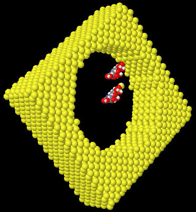
To ensure the protonic conductivity and contrary to a previous solution consisting of filling pores with a Nafion® solution [12], a grafting method is describe here where the internal surface of the pores are covered with silane molecules bearing acid functions. This process is designed to mimic the supposed structure of Nafion® membranes and obtain significant proton conductivity. The N-[(3-trimethoxysilyl)propyl]ethylenediamine triacetic acid in the form of trisodium salt, commercially available from United Chemical Technologies Inc (UCT), was chosen for the first investigations. As the surface of PS is covered by an oxide layer, the classical process of silanization can directly be used. The first step consists of creating silanol functions (Si-OH) at the surface of PS. A soft process involving UV ozone cleaner has been successfully implemented. This process creates the desired functions without geometrical modifications contrary to a previous wet process needing an immersion into “Piranha” solution (mixture of a 80 % solution of pure sulfuric acid with 20 % of a 33 % aqueous solution of hydrogen peroxide) which induced membrane deformations. The grafting of silane molecules is then realized by immersing the hydrophilic porous membranes into a 1 % solution of the acid silane in ethanol for 1 hour (time empirically determined with conductivity measurements) at room temperature and ambient air. Figure 3 shows a molecular simulation of the process.
|
|
|
Figure 3. View of the molecular scale of silane molecules compared to a 6nm diameter PS pore. One of the molecule is grafted on the surface. Si (yellow), O (red), H (white), C (grey),and N (blue).
|
In order to replace -Na endings by -H endings to get the real carboxylic behaviour for the grafted function, membranes are immersed for 12 hours in a 20 % solution of sulfuric acid, then fully rinsed in deionized water. To complete the FC assembly, electrode and catalyst layers are added to the membrane. E-tek electrodes composed of a carbon conducting cloth filled with platinum (20 % Pt on Vulcan XC-72) were used as a H2 / O2 catalyst. A 1 µl drop of a 5 % Nafion®-117 solution provides, on each side, after the evaporation of the solvant, a proton-conducting link between the electrodes and the membrane. This amount of Nafion® solution used as glue is too small to fill the pores and does not contribute to the proton conductivity in the membrane. As the membrane borders are covered with a Cr-Au layer to collect current, it is important to make sure that the electrodes and the membrane plated borders are in contact.
Results and Discussion
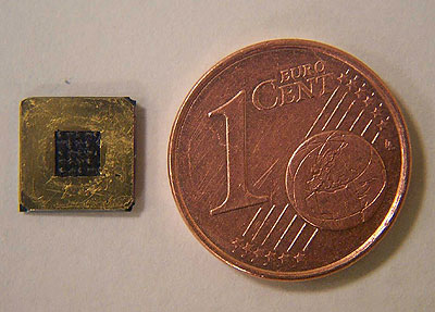
Figure 4 shows (top view) a typical 8 mm × 8 mm FC realized with an active area (in black on the figure) of 7 mm2. Geometrical parameters are not optimized but chosen to demonstrate the feasibility of the method.
|
|
|
Figure 4. Top view of a miniature fuel cell, scale comparison with a 1 cent (0,01 euro) coin.
|
When such a device is fed with hydrogen on one side and air on the other side a voltage appears between the two gold-plated sides and an electrical current can flow if a charge closes the circuit. Measurements are carried out at room temperature. H2 feeding is provided by a 20 % NaOH solution electrolysis and while O2 is provided directly by ambient air.
In order to bring the gas to the membrane, a home-made test cell was used in which the membrane electrodes assembly is mounted. Moreover, it enabled the measurement of electrical contacts on each side of the membrane and the evacuation of gas exhausts. The test cell was electrically connected to a voltmeter and an ammeter with a variable resistive load. Measurements with a Nafion®-filled PS membrane previously reported in [12] have been added to the I-V characteristic of the grafted porous silicon membrane for comparison. A current density of 118 mA/cm2 in minimal charge and 470 mV for open circuit voltage was obtained (figure 5).
|
|
|
Figure 5. Performances of a grafted PS fuel cell (red) compared with a Nafion®-filled one (blue).
|
These performances were preserved for 6 hours as long as the assembly was supplied with H2. The same cell has also been tested several times after these first measurements and has reached the same performances. The ageing of the device has not been measured yet.
If the performances achieved with both solutions are comparable in terms of power density (17 mW.cm-2 for the grafted membrane and 18 mW.cm-2 for the Nafion®-filled membrane) and current density (respectively 118 mA.cm-2 and 101 mA.cm-2), the open circuit voltage of the grafted membrane is much lower than the one of the Nafion®-filled membrane. This can be explained by the cross-over of gas through the grafted porous membrane. Indeed with this solution pores are not completely filled and the substantial gas diffusion through the membrane induces partial reverse voltage.
This difference of behaviour proves that the proton conduction through the membrane is realized in a new way, essentially by surface conductivity between the carboxylic functions grafted at the surface of the pores. The cross-over should be reduced, in future experiments, by decreasing the pore diameter to a value closer to the assumed one in Nafion® structure.
A comparison of the slopes of both I-V curves in the linear regime shows clearly a lower slope with the grafted membrane indicating a better conductivity than obtained with Nafion® filling. This present gain of 2.66 has not yet been optimized.
The effects of the possible artefacts inherent in the present technology will now be discussed. The key argument is the success of the functionalization of the porous silicon membrane to allow the proton conduction and the performances of the fuel cell should be closely related to the quality of this grafting. Without having yet obtained the chemical characterization of the monolayer grafted on the surface of the pores, the experimental fact is that such a membrane conducts the protons because the fuel cell is able to deliver an electrical current through an external resistor. That is not the case with the same kind of cell realized with a non-grafted porous membrane.
Contrary to a Nafion®-filled membrane the hydrophilic pores of the grafted membrane are only filled with water and not by the Nafion® used for the assembly with the electrodes as proved by the decrease of the open circuit voltage due to the diffusion of gas through the pores of the membrane. The conductivity cannot be produced by ionic species which would be eventually dissolved into the water of the pores because the intensity of the current is stable for many hours (with a classical diffusion coefficient of 10-5 cm2.s-1 the diffusion time of ions on a length of 50 µm is about a few seconds). To complete this analysis conductivity measurements were realized on similar membranes by mechanical application of electrodes directly on each side of the membrane and prove the intrinsic conductivity of the membrane. But as this method is at the present time destructive, it cannot be implemented on the membrane used to build the cell.
Another important point concerns the comparison of the starting current and the stability for both configurations as shown on the figure 6. The delay observed (170 s) since the start of the hydrogen generator (time=0 s) is due to the diffusion of hydrogen that should access the anode. The response time of the grafted membrane (<30 s) is shorter than the response time of the Nafion®-filled one (300 s). Contrary to ionomeric membranes, no hydration is required for the grafted membrane to conduct the protons. Another advantage of the grafted membranes (seen on the same figure) is the stability of the intensity of the current. It is experimentally shown better than for a Nafion®-filled fuel cell.
|
|
|
Figure 6. Current as a function of time achieved by a grafted PS fuel cell (red) compared with the one achieved with a Nafion®-filled one (blue).
|
Conclusions
In conclusion, this technique already appears to be able to produce small size fuel cells with high performances (starting time, stability, current density) which are easily integrable on silicon at low cost without the help of any ionomer film as a proton-conducting membrane. Furthermore, it is reasonable to expect better performances will be achieved following a reduction in pore diameter and the grafting of new molecules.
References
1. International Roadmap for Semiconductors, executive summary. Technical report, SIA.
2. Hebling C., “Portable Fuel Cell Systems”, Fuel Cell Bulletin 46 (7) (2002) 8-12.
3. Lu G.Q., Wang C.Y., Yen T.J., Zhang X., “Development and Characterization of A Silicon-Based Micro Direct Methanol Fuel Cell”, Electrochim. Acta 49 (5) (2004) 821.
4. Kelley S.C., Deluga G.A., Smyrl W.H., “Miniature Fuel Cells Fabricated on Silicon Substrates”, AIChE J. 48 (5) (2002) 1071.
5. Motokawa S., Mohamedi M., Momma T., Shoji S., Osaka T., “MEMS-Based Design and Fabrication of A New Concept Micro Direct Methanol Fuel Cell (µ-DMFC)”, Electrochemistry Communications 6 (2004) 562-565.
6. Yu J., Cheng P., Ma Z., Yi B., “Fabrication of Miniature Silicon Wafer Fuel Cell with Improved Performances”, J. Power Sources 124 (2003) 40-46.
7. Bunker C.E., Ma B., Simmons K.J., Rollins H.W., Liu J., Ma J., Martin C.W., DesMarteau D.D., Sun Y., “Steady-State and Time-Resolved Fluorescence Spectroscopic Probing of Microstructures and Properties of Perfluorinated Polyelectrolyte Membranes”, Journal of Electroanalytical Chemistry 459 (1998) 15-28.
8. Halimaoui A., in Properties Of Porous Silicon, edited by L. Canham, published by INSPEC, vol. 18 (1997).
9. Lehmann V., Electrochemistry of Silicon, Wiley-VCH, 2002.
10. Angelucci R., Poggi A., Dori L., Cardinali G.C., Parisini A., Tagliani A., Mariasaldi M., Cavani F., “Permeated Porous Silicon for Hydrocarbon Sensor Fabrication”, Sensors and Actuators A 74 (1999) 95-99.
11. Splinter A., Stürmann J., Benecke W., “Novel Porous Silicon Formation Technology Using Internal Current Generation”, Mat. Sc. and Eng. C 15 (2001) 109-112.
12. Pichonat T., Gauthier-Manuel B., Hauden D., “A New Proton-Conducting Porous Silicon Membrane for Small Fuel Cells”, Chem. Eng. J., 101, 1-3 (2004) 107-111.
|