The height histogram of a topographical image presents the statistical distribution of z-values (heights) within the image. The histogram is a graph of neighboring columns (or bins). In the histogram, each column depicts a height range. The height of each column represents the number of image pixels which have a height value in the particular range. All columns have the same width meaning that they represent the same height span. As shown in Figure 1, usually the columns are so narrow that the histogram looks like a filled 2D graph.
The histogram will be bell shaped with the bell top at the mean height in the image if the surface is random. The histogram will have two distinct peaks each centered on the respective height levels if the surface has two distinct levels as in the instance of a height calibration standard. The height histogram of an image dominated by surface tilt will be flat with all columns roughly equal in height.
A pair of cursors (markers) can be used to read out the positions of peaks in the height histograms In SPIP™. Each marker represents a certain height level. SPIP™ evaluates the amount of material and void between the markers.
Material volume is the volume limited by the lower marker and by either the upper marker or by the surface, whichever is smallest in height at each image pixel position.
Void volume is the volume limited by the upper marker and by either the lower marker or by the surface whichever has the highest z-value at each pixel position.
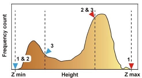
Figure 1. Illustration of the histogram of an image with two distinct height levels. The dashed lines represent different marker positions.
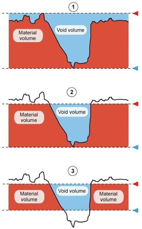
Figure 2. A surface represented by a section profile, with the markers from Figure 1 and with material volume (red) and void volumes (blue) indicated.
Special Cases
The sum of the material and void volume will be equal to the image projected area times the image z-range when the markers are placed at the boundaries of the histogram. Both the material and the void volume will ideally be zero when the markers are on top of each other. However, due to the histogram resolution, they often end up with a small but finite value.
Example
Using the Histogram for Measuring the Volume of Pits
A 3D projection view of a calibration grating imaged by AFM is shown in Figure 3. The pits are approximately 107 nm deep. The lateral dimensions of each pit are approximately 4.1x4.8 µm2, measured from the image using a profiling tool on a single pit. This gives a single pit volume of about 2.1 µm3.
In Figure 4, the corresponding height histogram is represented. To measure the volume of all the pits, the lower cursor marker (blue triangle) has been set to the minimum height value and the upper marker (red triangle) has been set just below the surface level. When the cursor markers are moved in the histogram, the boundaries of the color bar in the active image window are moved simultaneously such that only surface between the markers are shown with the chosen color coding. Refer to Figure 5 (bottom) to understand that what is below takes the lowest color in the color bar and what is above takes the highest color in the color bar.
The void volume calculated in the histogram is about 25 µm3. As shown in Figure 5, the Polygon Measurement Tool has been used for calculating the volume of a single pit. The result is about 2 µm3 not far from the 2.1 µm3 measured “manually” using the profiling tool. A crude count of the number of complete pits is approximately 13. Multiplying this with the evaluated single pit volume using the Polygon Measurement Tool produces 26 µm3. This is consistent with the void volume found in the histogram, taking into account the spread in pit volumes and the uncertainty in the manual estimate of the number of complete pits.
Using the same method, histograms can be used for measuring the volume of protrusions.
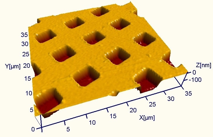
Figure 3. 3D projection of the AFM image of a calibration grating
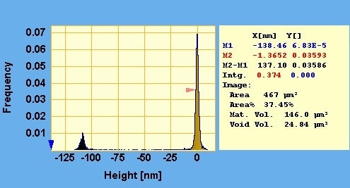
Figure 4. Height histogram. The lower cursor is set at the minimum height value in the image and the upper cursor marker is set just below the upper peak which represents the surface level – or the bearing plane. The average pit depth taken as the height distance between the two peaks (not the cursors) is about 107 nm
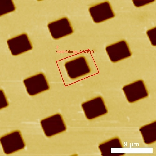
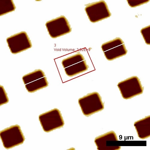
Figure 5. Top: Color coded view of the image from Figure 3. The red box shows the volume measurement of an individual pit using the Interactive Measurement Tools in SPIP™. Bottom: Color coded view but after the cursor markers in the histogram has been set. It is seen that the top-level surface is all white due to the cropping of the color scale at the height level of the upper (red) cursor in the histogram

This information has been sourced, reviewed and adapted from materials provided by Image Metrology A/S.
For more information on this source, please visit Image Metrology A/S.